
PCB Mill
A desktop PCB mill designed for 50x70mm PCBs!
Total time: 13 hrs
July 31 - 1 hr
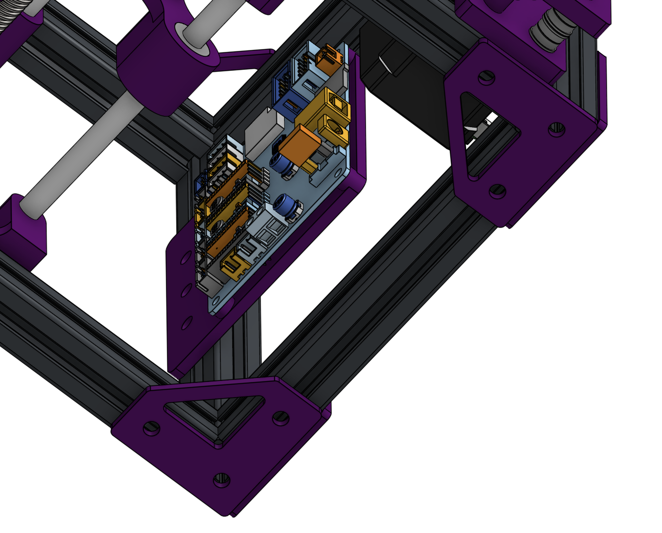
I was told the corners wouldn't hold, which made me realize I didn't add corner brackets. I added those on every corner, along with a mount on the back for the cnc controller I am using. I also realized that 2020 extrusions were perfect for m5 screws, so i updated some parts and my bom to use m5 screws and add the PSU that I forgot to add.
July 19 - 3 hrs
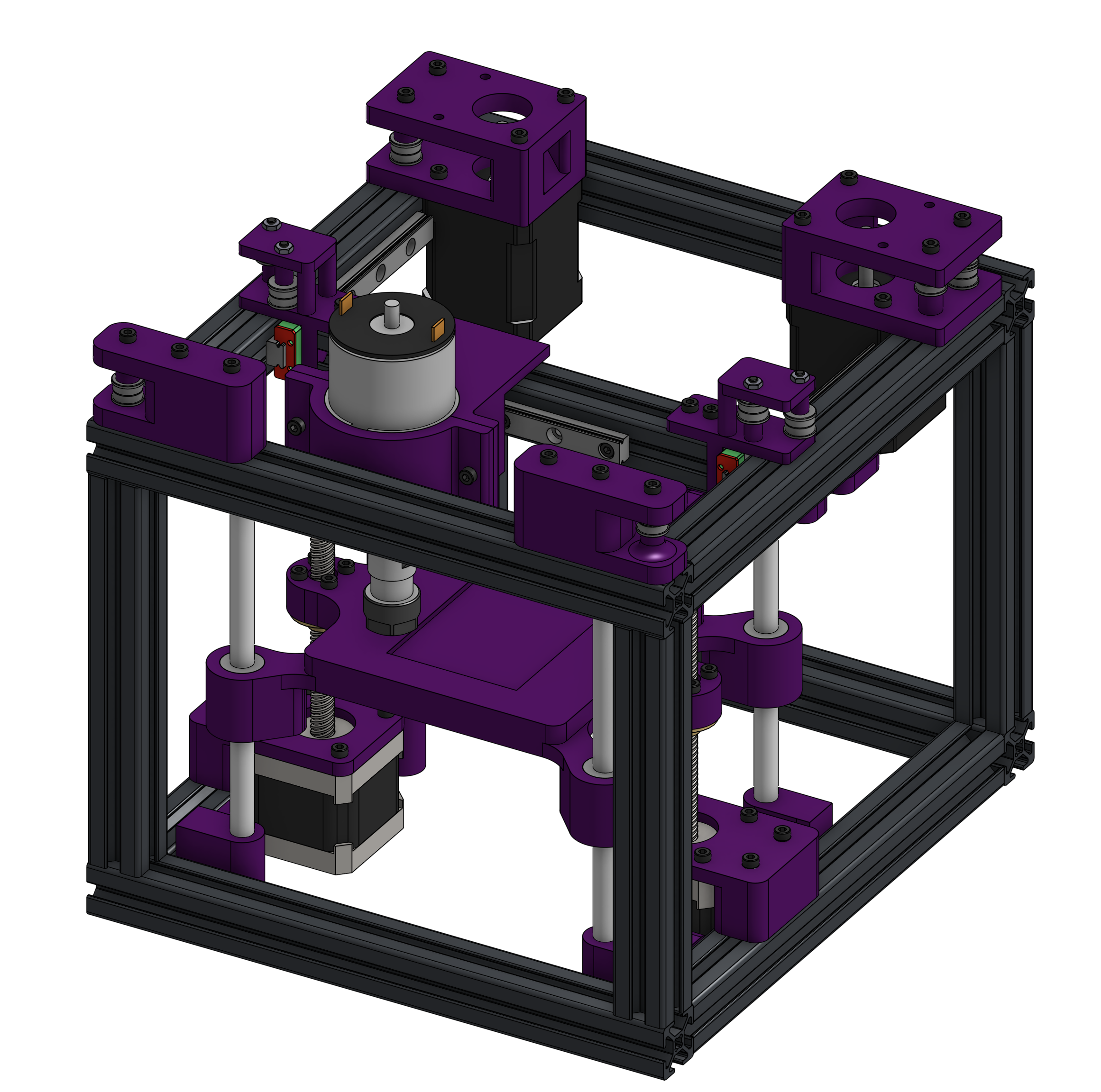
Finished BOM, using most parts from alixpress. I finished the z axis design and mated all of the screws.
July 8 - 2 hrs
Worked on the z-axis design. I decided to use linear rods over rails for this axis, as the mounting seemed simpler. I am using nema17s with 100mm leadscrews to power this axis, and I'm using a large 3d printed bed with a 50x70mm cutout as the bed for the cnc.

June 30 - 4 hrs
I started designing the y-axis, and I noticed there was an issue with the linear rails in the configuration, so I edited them. I went back and fixed the x-axis to use these updated rails, from which I gained a few more mm of length. I decided to use the voron belt path for the corexy, as I was familiar with it. This axis also uses linear rails for compactness. I am using nema17 motors, as they are relatively small enough to use in such a small machine.

June 24 - 3 hrs
I started off by desigining the x-axis for the PCB mill. I decided that I would make the machine a belted corexy so it would be easy to convert into a generic corexy platform in the future. I decided to use linear rails over rods for the x-axis, as they are more compact. I also decided to use a 775 spindle, recommended by another hackclubber, and designed a clamp mount for it as it has no mounting holes.
