
6 Axis Arm
6 Axis Robotic Arm - Journal
The Idea
Something I have been interested in for a while, is creating a 6 Axis Robotic arm, using simplistic materials to keep the costs low, while also maintaining accurate movements. From this project, I really want to get out a product that works, but also develop the following skills:
- PCB Design
- Finding Suppliers
- Clean Electronics
I'm already very proficient in CAD, using Solidworks from my robotics background.
Time Spent - 1 Hour 20/5/25
Research into Existing Industry Solutions
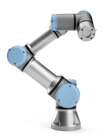
UR3 - 25,000USD
- All-metal construction (aluminum and steel), with integrated high-resolution encoders and harmonic gear drives for each joint.
- Payload: 3 kg (6.6 lbs).
- Reach: 500 mm (19.7 in).
- Repeatability: ±0.03 mm — very high
- Integrated Servo Motors with Closed Loop Feedback
✅ Advantages
- VERY Precise - Fit for Industrial applications
- Integrated in an eco system which allows it to be commercially deployable.
❌ Disadvantages
- VERY expensive which makes it non viable for hobby or educational use
- Not suitable for heavy loads
Time Spent - 2 Hours - Date: 21/5/25
Research into Existing 3D Printed/DIY Solutions
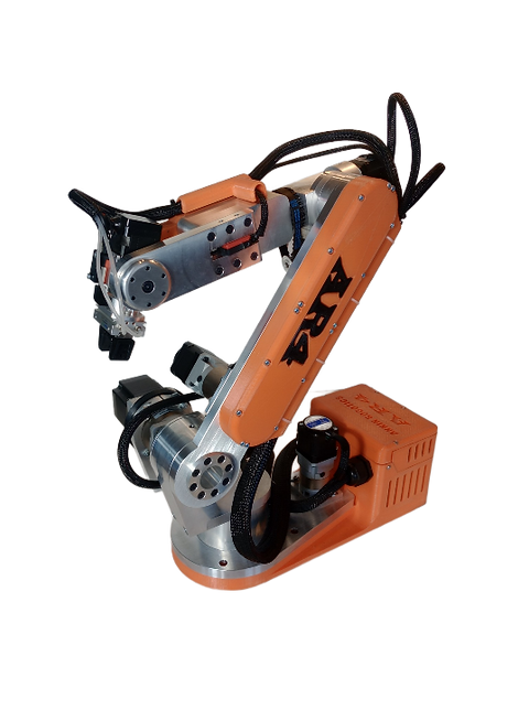
AR4 - 2000USD for a Full Kit
- The AR 4 has a primarily metal construction
- VERY Rigid
- Rated Payload: ~500g
- Stepper motors are all exposed
- Uses the StepperMotorOnline Gearboxes
- Less Backlash, Accurate Movements
- Use of High Quality Bearings
- Tapered Roller Bearing - This bearing construction accommodates combined loads and provides low friction during operation.
- Utilises NEMA stepper motors (NEMA 17 and NEMA 23)
✅ Advantages
- High Rigidity, prompting high repeatability and accuracy
- Cost-effective compared to industrial robot arms
❌ Disadvantages
- High cost for a DIY project with the use of billet aluminium and complex bearings
- The aluminium increases weight away from the pivot points, decreasing max payload, and speed of motor
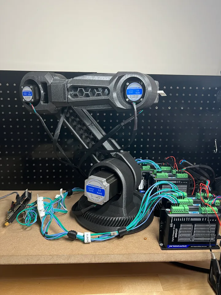
Fully Printed 6 Axis Arm (Printables)
- Fully 3D printed
- Exposed motors
- Kinda messy wiring/no real path for it to take
- Use of gear on the bottom, with a detached stepper motor
- Use of NEMA23 and NEMA17
- External unit drivers, makes the solution alot bigger
- Uses 3D printed planetary
✅ Advantages
- Cheap with the 3D printed parts
- Easy to make
- Low cost gearboxes
❌ Disadvantages
- Sacrifices alot of rigidity with long runs of 3D prints
- Very large footprint
Time Spent - 2 Hours Date: 22/5/25
Definition of Project
After reviewing the previous product, I set out some definitions of what my project would look like.
Mechanical/Electrical
- Rigid, making precise movements
- Low Backlash to make repeatable movements
- Cheap - Mainly 3D printed (including gearboxes, they retail for 40USD each, while adding alot of weight)
- Make efficient use of bearings, they contribute weight as well.
- Have clean, and maintainable electronics, allowing for easy troubleshooting.
- Make use of a custom PCB to drive all motors
- Bonus: Closed Loop Control on Steppers
Software
- Powered by an ESP32-S3
- Controlled through a PS5/Xbox controller
These objectives also allow me to form a criteria for success, allowing the project to have basis for evaluation, leading to increased success.
Time Spent - 1 Hour Date: 23/5/25
Design - Day 1 - Actuator
For the design of the actuator for the first 3 joints, I knew I wanted to use a NEMA17 motor, keeping it simple, and lightweight. Some of the constraints that I faced were as follows:
- Accurate with Low Backlash
- Easy to Manufacture - 3D prints
- Cheap
- Able to package in a small form factor.
- Serviceable
In order to accomplish this, I took inspiration from a design on Printables, (https://www.printables.com/model/132262-robot-actuators) which seemed to meet some of the criteria I needed. Yet, I saw some flaws with the way in which the bearing works, and lack of planet carrier.
Having the bearing constructed from the BBs introduces margin for incorrect tolerance, while also not being serviceable inside, as the insertion of the BBs causes it to lock.
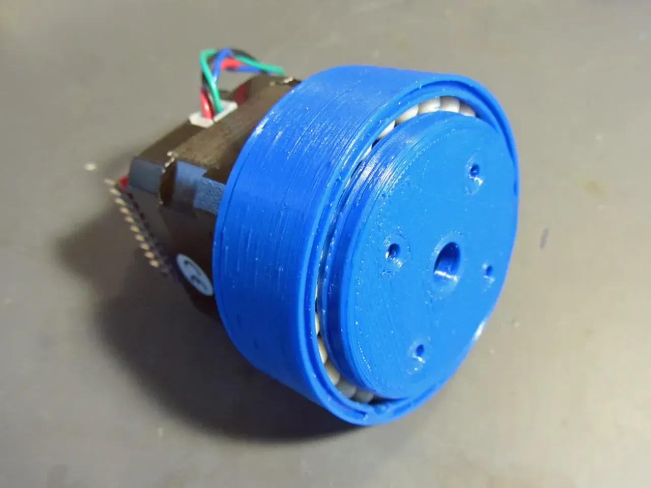
In order to combat this, I chose to use a large thin section bearing in place, sourced from Alibaba. The X-Contact in the bearing makes it optimal for both Axial and Thrust loads, which is crucial for this application.

Additionally, inside I wanted to implement a planet carrier, with each planet having a bearing to spin around, increasing the efficiency of the gearbox.
Internally, the planetary gearbox makes use of helical dual-stage planets to allow for a 38:1 ratio. Another problem that comes up with 3D printing the gears, however; is the lack of precision, which can cause them to need to be printed at a smaller size, decreasing tooth connection, and thus increasing backlash. I didn't view this as acceptable. Thus, I decided to explore 2 options, both with the aim to combat the backlash.
Firstly, I took some more inspiration from the creators other designs, and created a similar expanding outer ring, allowing it to flex under the irregularities in the tooth profile, decreasing backlash as the gears can be printed bigger. I'm also going to look into JLC3DP SLA services, to have the gears be printed more accurately. Compounding both these should hopefully allow for a desirable result.

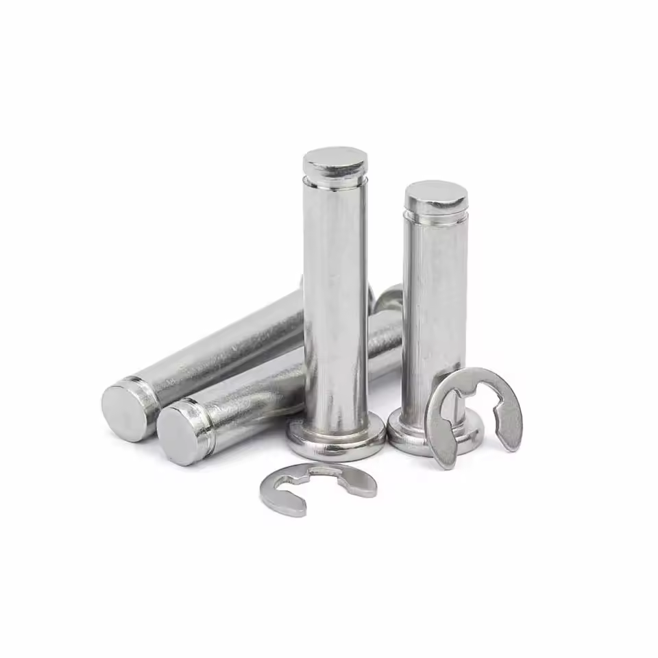
For the planet carrier I integrated it into the output ring, with 2 5x11x5 bearings per planet. Initially, they were supported by a 3D printed rod coming down from the top, but early on I identified this as a shear point, and rather will use a steel shaft, with a e-clip at the end. This will allow for a much more rigid solution, and reduce the chance of failure.

I'm overall pretty happy with how the actuator has turned out so far, I'm going to work further on the mounting pattern once more of the project becomes defined, and modify it to the needs.