Customized Ai Electric Wheelchair
Created by
@prisca7c
Wheelchair Project Journal!
TITLE: Customized AI Electric Wheelchair
AUTHOR: PRISCA CHIEN (U0741Q95Y02)
DESCRIPTION: my own motorized wheelchair with ai
CREATE DATE: July 27
Prisca: 89 hours
Updated until: Aug 10
🗓️ July 27 - 12 hrs
- started researching all the parts i need for my ai-powered electric wheelchair project. looked into battery options and decided on 24v lithium-ion packs because theyre lighter than lead acid and last longer. need about 50ah for decent runtime. specifically looking at 18650 cell packs with bms built in. calculated that at 5a continuous draw i should get around 10 hours runtime which is way better than the 4-6 hours most commercial wheelchairs get.
- spent time comparing brushless vs brushed dc motors for the wheels. brushless are more efficient but brushed are simpler to control. need enough torque to handle going up hills with a person on it. looking at 24v 350w motors with at least 80nm stall torque. found some decent planetary gearbox motors on alibaba but shipping is expensive. might go with standard wheelchair hub motors instead since theyre already designed for this application. made a list of all the external stuff i need like joystick controller, magnetic armrest mounts, control panel with buttons, battery box, and custom circuit board. for the joystick im thinking analog hall effect sensors since they dont wear out like potentiometers. need at least 10-bit resolution for smooth control.
- figured out the communication setup - raspberry pi handles the ai and camera stuff, talks to my custom pcb via i2c or spi, which talks to an atmega2560 microcontroller for the main motor controls and safety systems, and an esp32 for wireless communication with phone app and remote monitoring. might add can bus later if i need more robust communication.
- looked at other peoples wheelchair builds online for ideas on how to lay everything out and manage all the wires. found some good ideas about using spiral cable wrap and making modular harnesses that can be unplugged for maintenance.
- biggest problem was finding parts with the right connectors and comparing prices from different suppliers. mouser and digikey are expensive but reliable, alibaba is cheap but quality is questionable. also realized i dont know much about protection circuits yet, especially for high current motor drives.
- next up is finalizing the exact parts list with all the technical specs and footprints.
🗓️ July 28 - 15 hrs
- focused on protection circuits today. learned about tvs diodes for surge protection - need bidirectional ones rated for at least 28v to handle the 24v rail spikes. schottky diodes to protect against back voltage from motors when they act like generators during braking. using 40v 10a schottky diodes on each motor output. also figured out capacitor sizing - need big electrolytic caps (1000uf+) on each voltage rail for bulk storage and smaller ceramic caps (100nf) right at each ic for high frequency noise filtering.
- decided which parts should be separate modules vs built into the main board. keeping motor drivers as separate modules because they get hot and might need replacement. also making the buck converters modular so i can swap in different voltages if needed. raspberry pi obviously stays separate. everything else like the atmega2560, esp32, and analog circuits goes on the main board.
- made almost final list of all electronic parts with exact part numbers and where to buy them. motor drivers are cytron md30c because theyre robust and have good current sensing. buck converters are lm2596 modules from aliexpress. for the microcontroller im using atmega2560 in qfp package because it has enough io pins and hardware pwm channels. esp32 is the wroom-32 module.
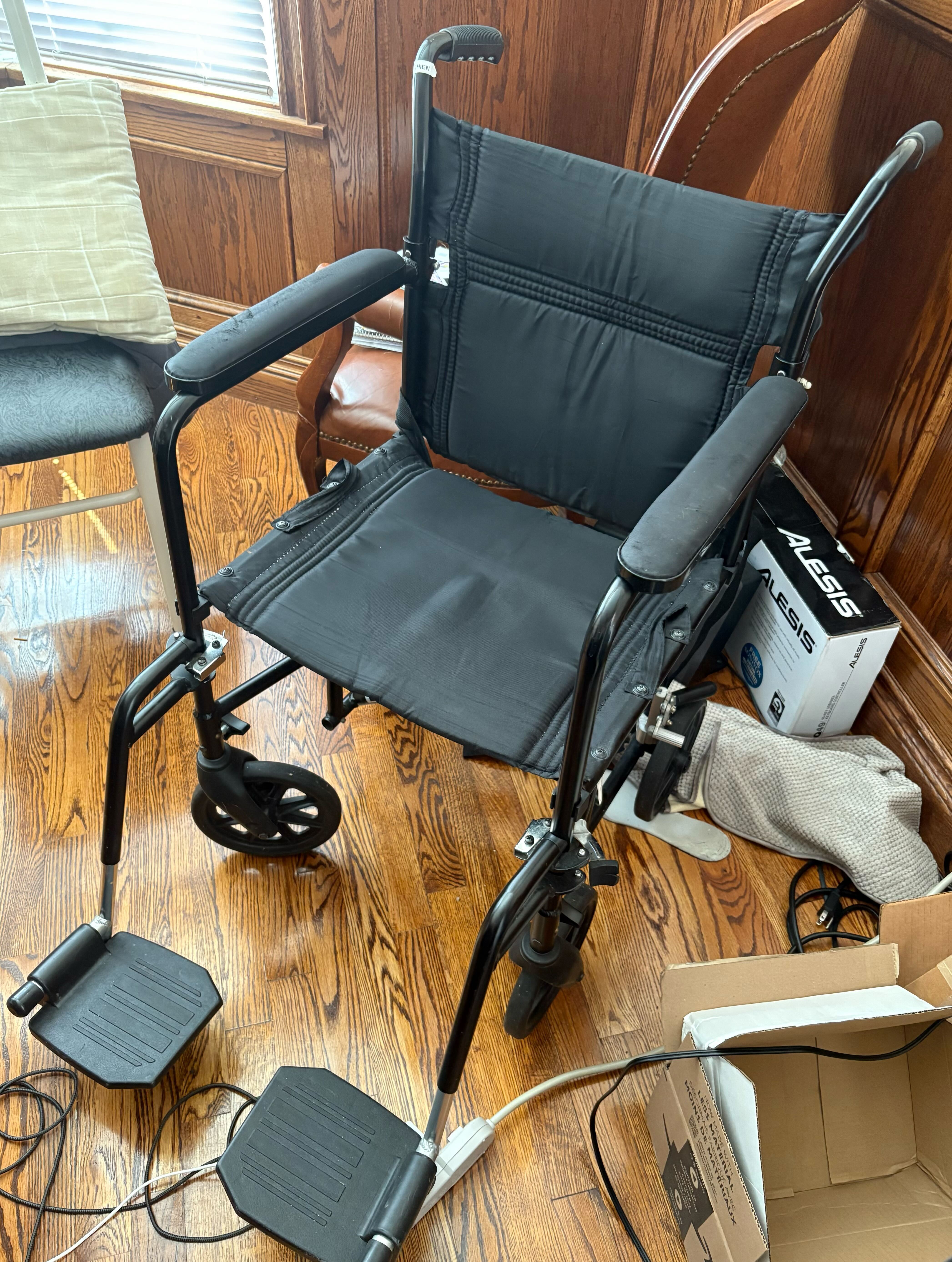
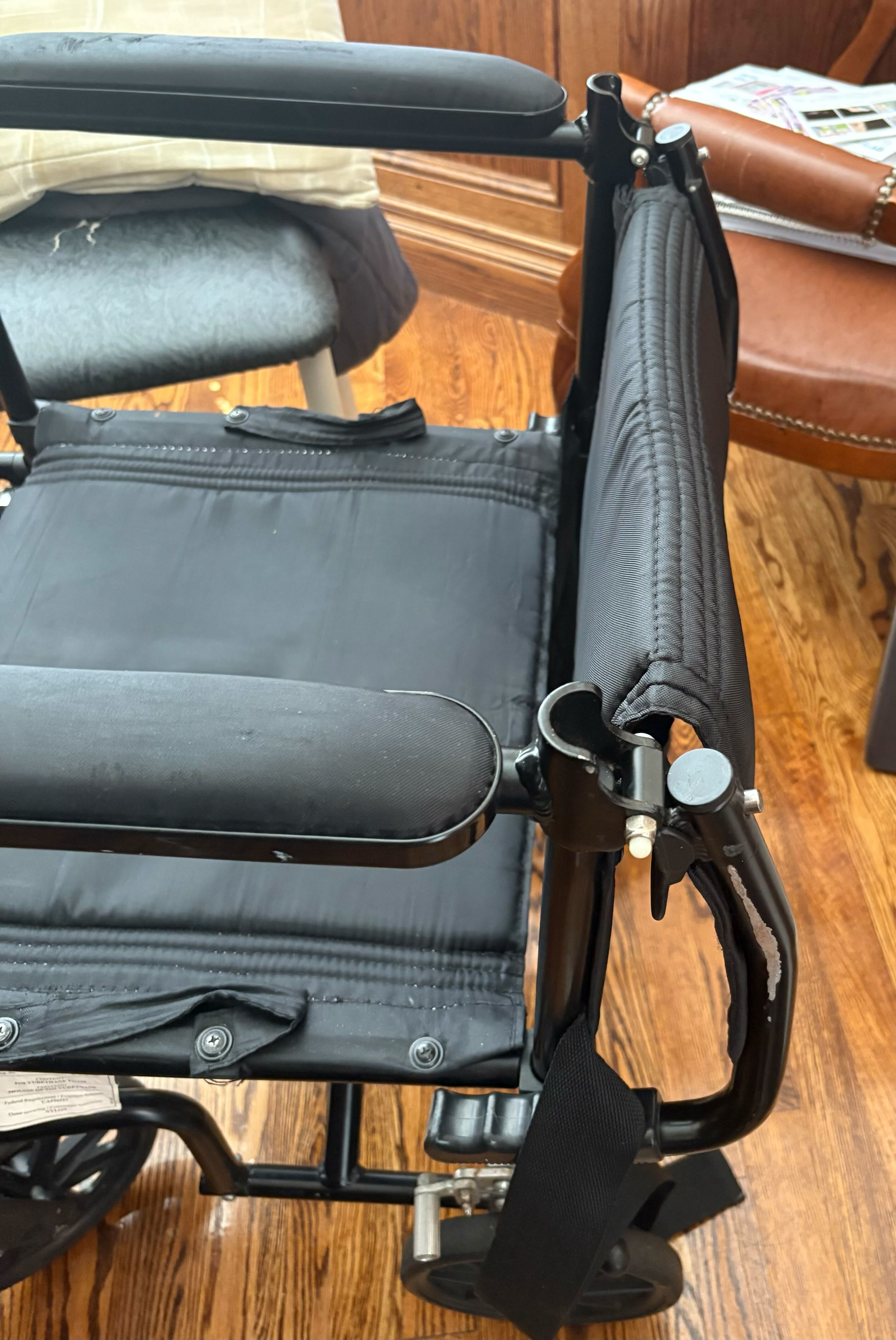
- took measurements of the actual wheelchair so i can design the 3d printed parts to fit. wheelchair frame tubes are 25mm diameter, seat is 18 inches wide, armrests are 24 inches long and 2 inches wide. battery box needs to fit under the seat without interfering with leg room.
- realized the power traces on the circuit board might be too thick for the available space. for 10a continuous current need at least 0.2 inch wide traces on 1oz copper but that takes up too much room. might need to use copper pours instead of just traces, or go to 2oz copper thickness.
- feel good about understanding surge protection now. ready to start drawing the schematic.
🗓️ July 29 - 17 hrs
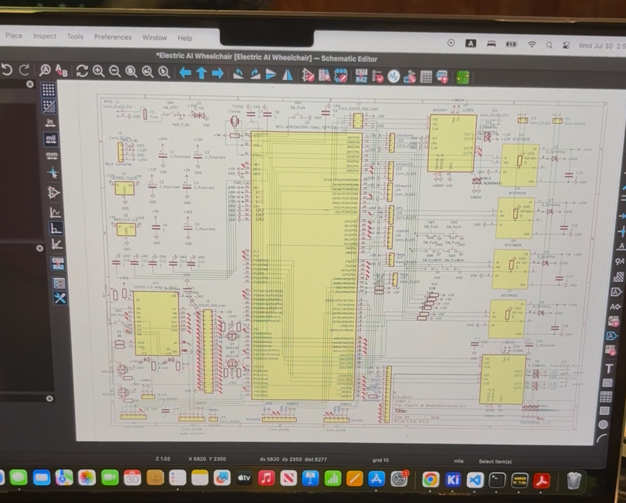
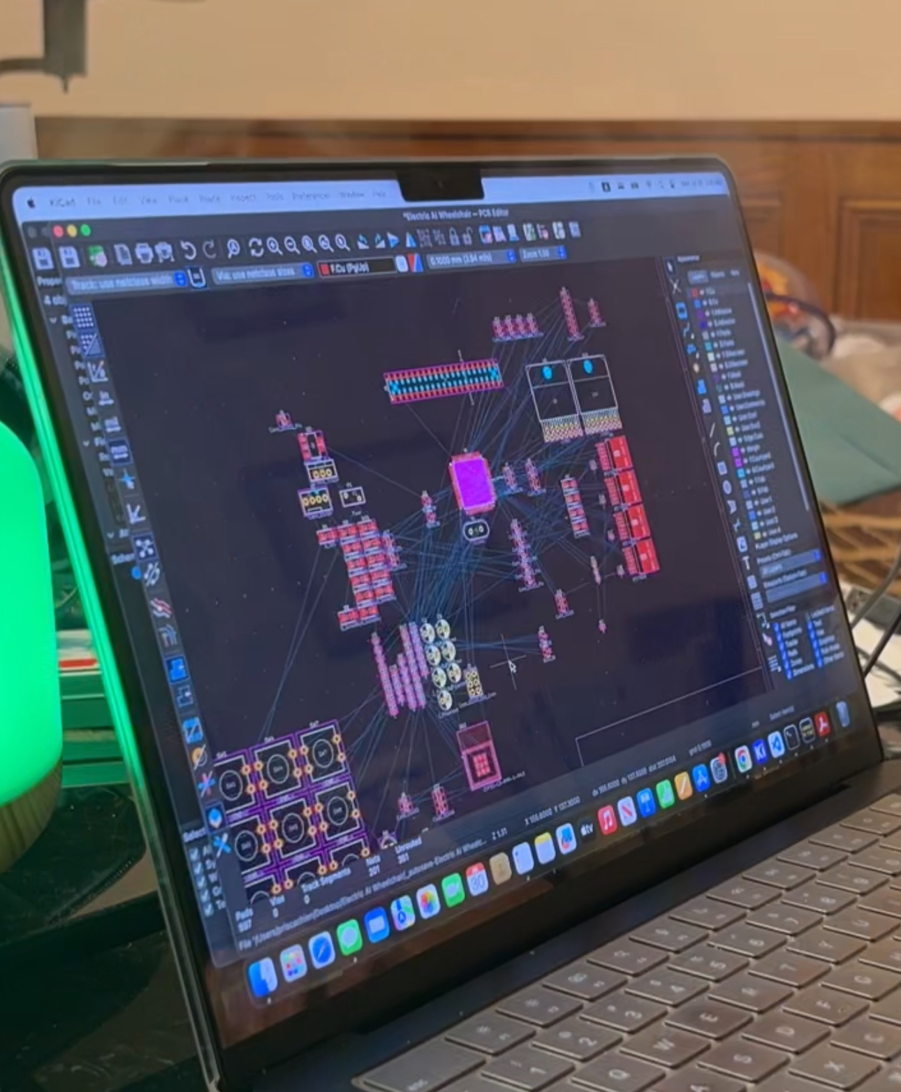
- started designing the circuit board schematic in kicad. put the atmega2560 in the center with all the other circuits around it. used hierarchical sheets to organize different subsystems - power management, motor control, communications, and sensors each get their own sheet.
- added all the components i researched earlier. power section has main 24v input with reverse polarity protection using a p-channel mosfet, then branches to 12v and 5v buck converters. 12v rail powers the motor drivers and cooling fans, 5v rail powers all the logic circuits and raspberry pi. for the atmega2560 i used the 100-pin tqfp package and broke out all the important pins - pwm outputs for motor control, analog inputs for current sensing, digital io for switches and status leds, and hardware serial ports for communication with raspberry pi and esp32.
- esp32 section includes the crystal oscillator, power supply filtering, and gpio breakouts for the wireless antenna connection. also added programming header so i can update firmware without removing the chip.
- analog section has op-amps for current sensing with precision shunt resistors, voltage dividers for battery monitoring, and adc filtering. used rail-to-rail op-amps since theyre running on single supply.
- finished the first version of the schematic with correct pin connections and labeled all the voltage rails (5v, 12v, 24v). double checked all the power calculations - worst case total current draw should be around 15a so 24v battery pack needs to handle that plus some safety margin.
- schematic looks solid but know the actual board layout is going to be tricky with all these connections. especially the high current motor traces and keeping the analog circuits away from switching noise.
🗓️ July 30 - 15 hrs
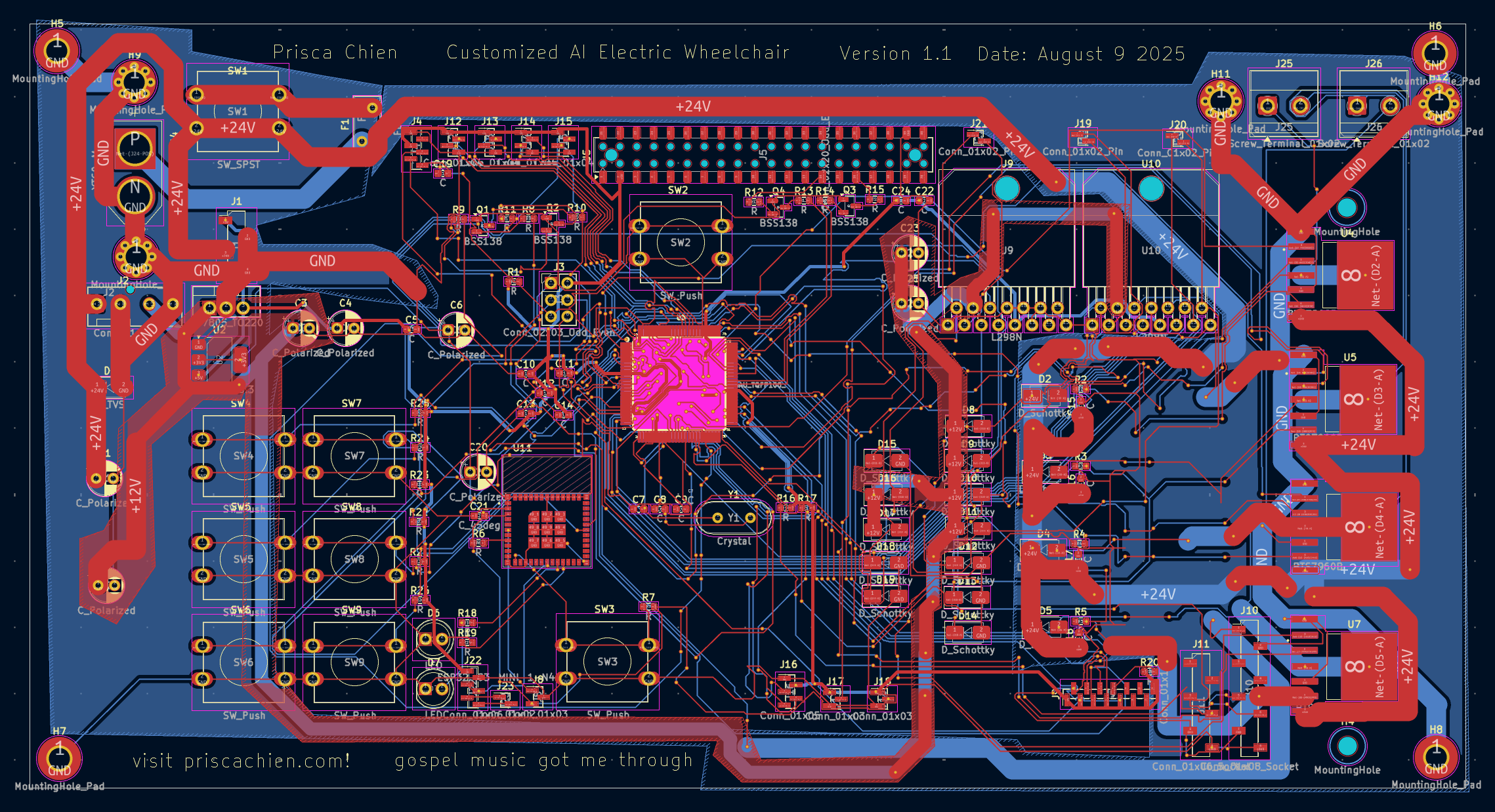
- worked on laying out the actual circuit board. decided on 4-layer pcb with top and bottom for components and signals, inner layers for power planes. board dimensions are 150mm x 100mm which should fit in the 3d printed housing.
- put power inputs on the left side with big screw terminals and fuses. power section with buck converters and protection circuits right next to the input. motor driver connectors on the right side with thick traces and copper pours for high current paths.
- kept the atmega2560 in the middle to minimize trace lengths to all the peripherals. crystal oscillator as close as possible to reduce noise. analog circuits in bottom left corner away from switching power supplies and digital circuits.
- positioned raspberry pi connector (40-pin header) and esp32 chip where theyll be easy to access from the housing openings. usb programming connector for atmega on the edge of the board.
- routing was a nightmare. started with power traces first - 24v, 12v, 5v, and ground. used 0.5mm traces for low current stuff, 1mm for medium current, and 2mm plus copper pours for high current motor connections. ground plane on inner layer with lots of vias for good connection.
- signal routing came next. high speed signals like spi between atmega and esp32 kept short with ground plane underneath. analog signals routed away from digital switching circuits. used differential pairs for critical signals where possible.
- finished routing all the traces but its super dense and complicated. had to use vias to jump between layers constantly. some traces had to snake around quite a bit to avoid crossing other signals.
- thinking i need more modular design for next version. maybe separate the motor drivers completely and use ribbon cables to connect them. would make the main board smaller and easier to route.
🗓️ July 31 - 14 hrs
- added mounting holes in each corner of the board with 3mm screws. also added mounting pads for any components that might need extra mechanical support like the big electrolytic capacitors and heavy connectors.
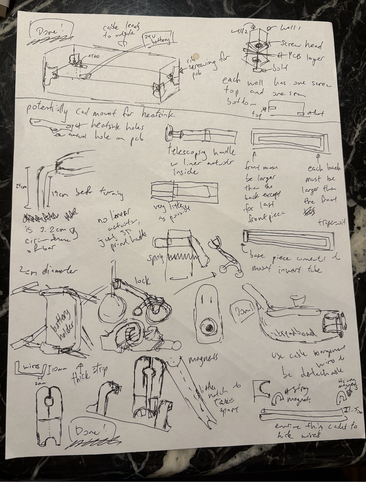
- decided to use copper pours instead of just thick traces for better heat spreading. 24v and ground get full copper pours on opposite sides of the board. 12v and 5v get smaller pours in their respective areas. this should help with both current carrying capacity and thermal management. designed all the 3d printed parts in fusion 360:
- magnetic armrest mount - uses 20mm neodymium magnets embedded in both the armrest and wheelchair frame mount. magnets are strong enough to hold the armrest securely but can be detached for transport. includes cable routing channels for the control panel wires.
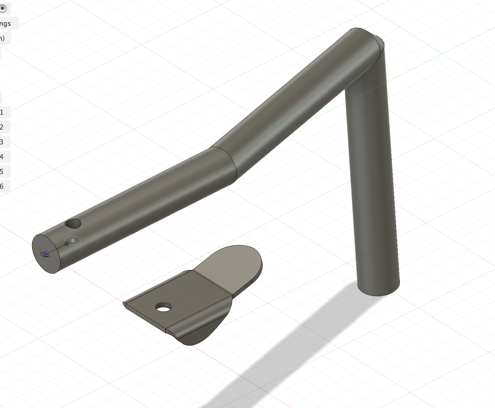
- walker handle with locking mechanism - modeled after standard wheelchair handles but with a spring loaded pin that locks into the frame. handle folds down when not in use. includes rubber grip and emergency stop button.
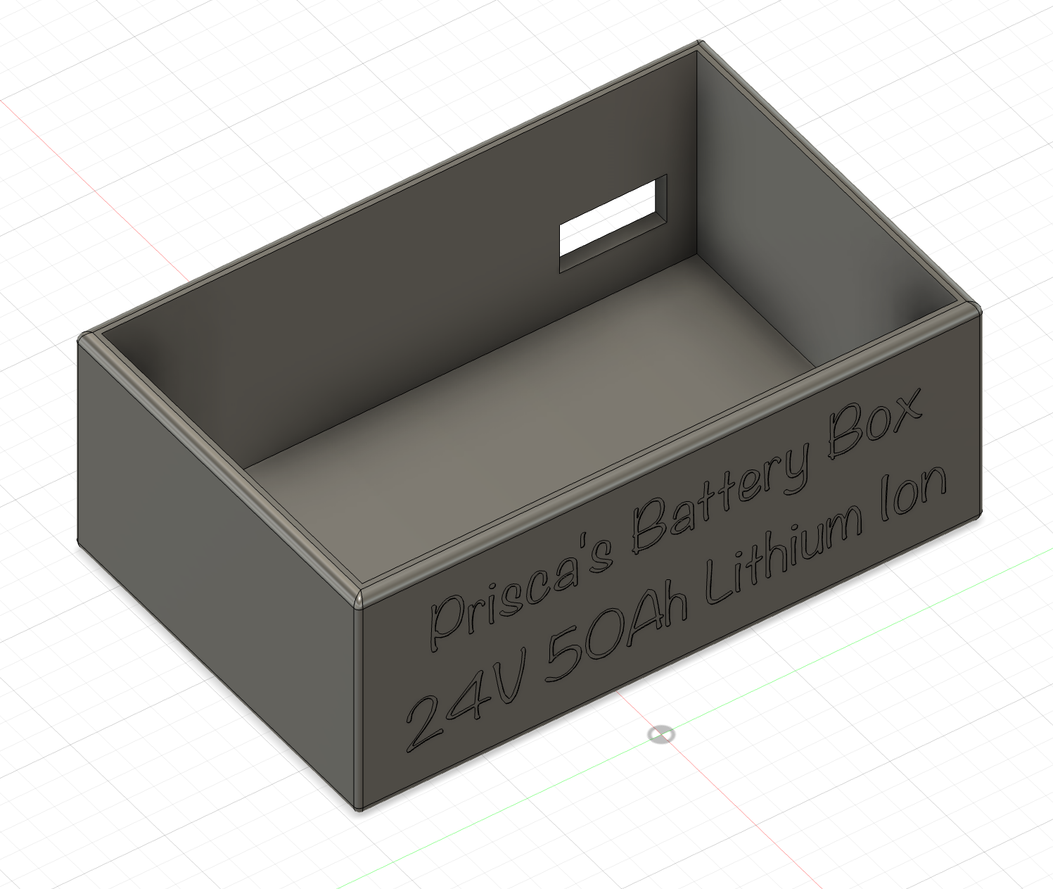
- battery box for 24v pack - completely enclosed box that mounts under the seat. has ventilation holes and a cooling fan. includes bms mounting area and main power switch. box is split into two parts for easier 3d printing.
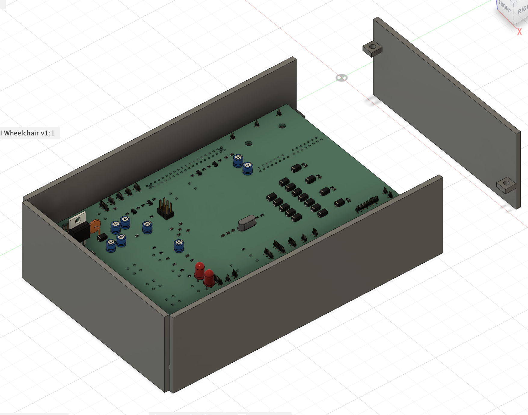
- pcb housing - two part enclosure with mounting posts for the circuit board. front and back are open for airflow and connector access. includes cable management features and mounting holes to attach to wheelchair frame.
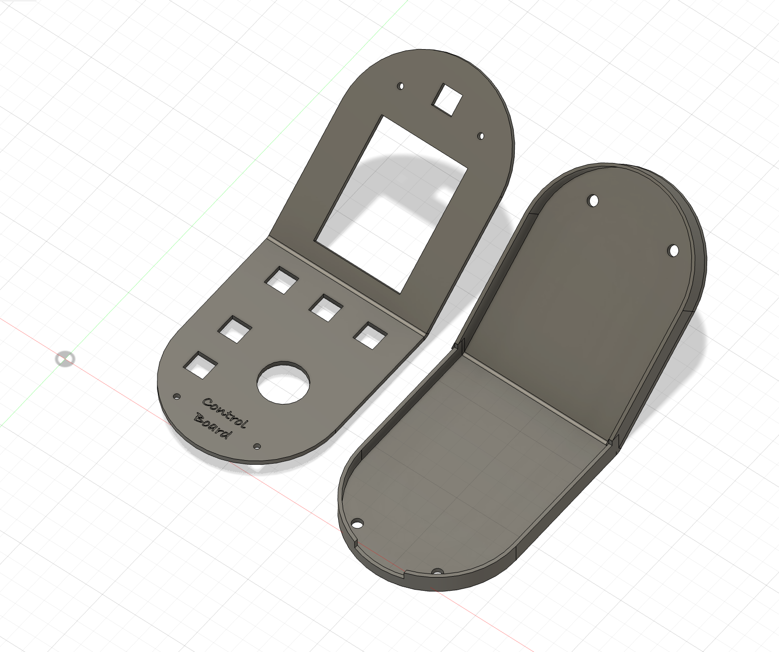
- control panel with 6 buttons plus analog joystick - waterproof membrane switches with tactile feedback. joystick is hall effect type for reliability. panel mounts to the armrest via magnetic connector so it can be removed for cleaning or replacement.
- created github repository
ai-wheelchair
to store all my design files. organized into folders for mechanical parts, electronics, firmware, and documentation. - all the mechanical parts need to work together with the electronics placement. spent time making sure connector locations on the pcb line up with cable routing in the 3d printed parts.
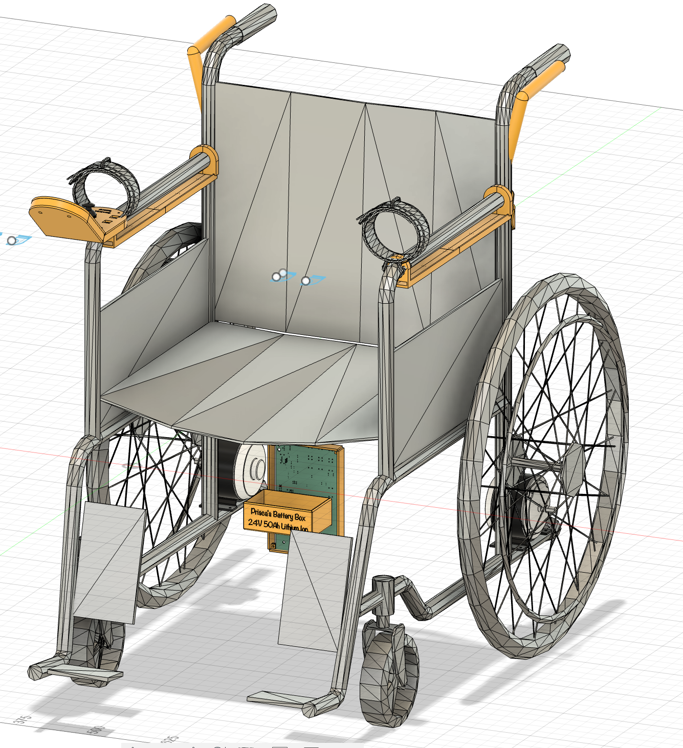
 ## Battery Box
 ## Close-up of PCB Wall
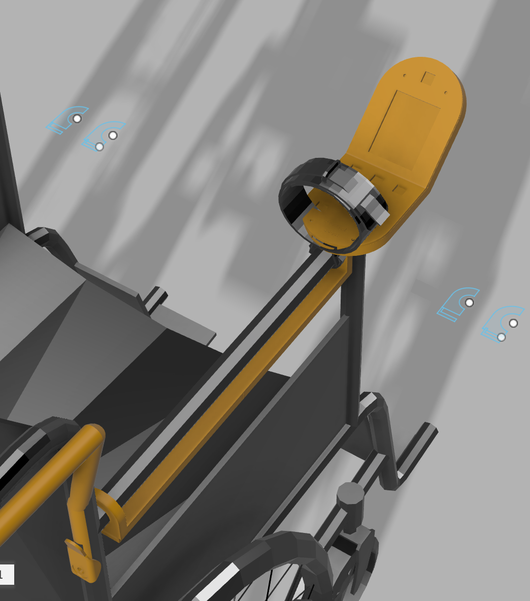
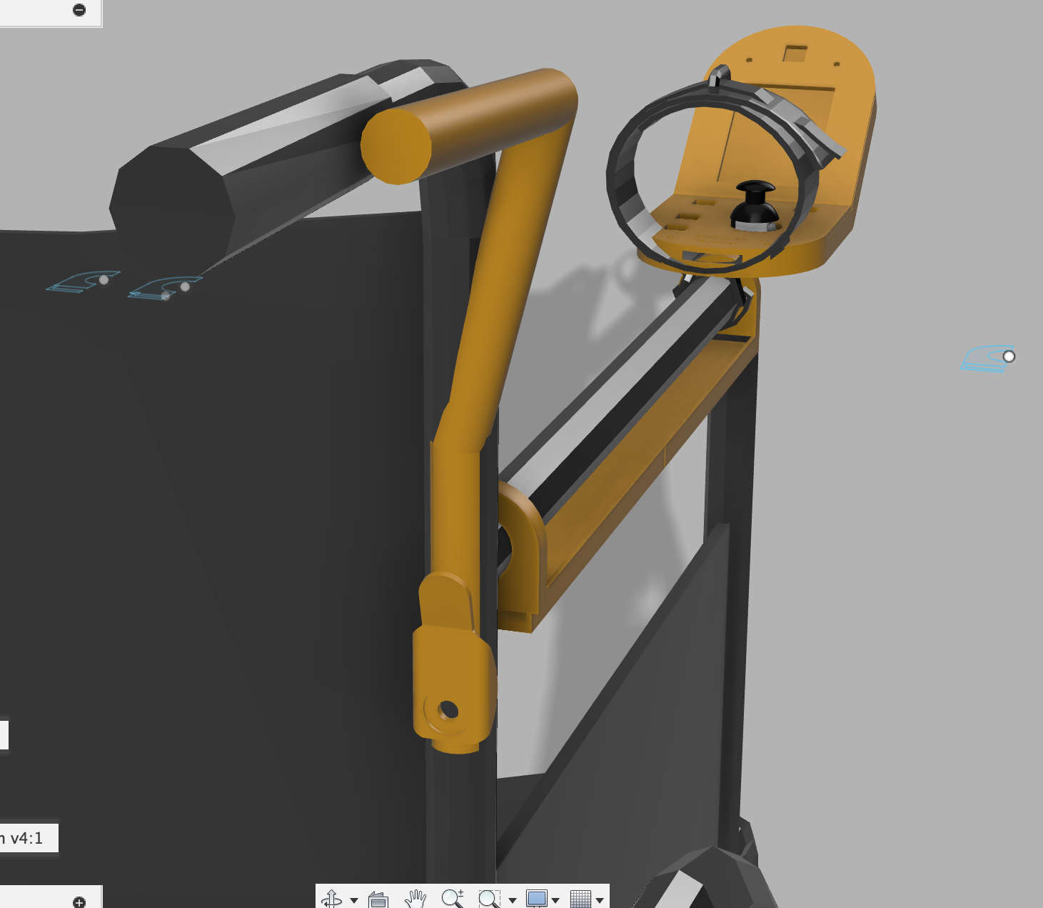
 ## User Control Panel (external modules connected here)
 ## Handle with Lock Mechanism
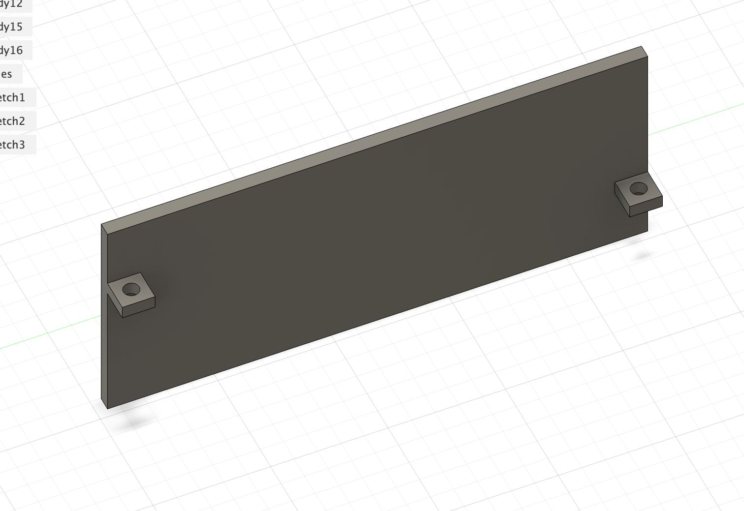
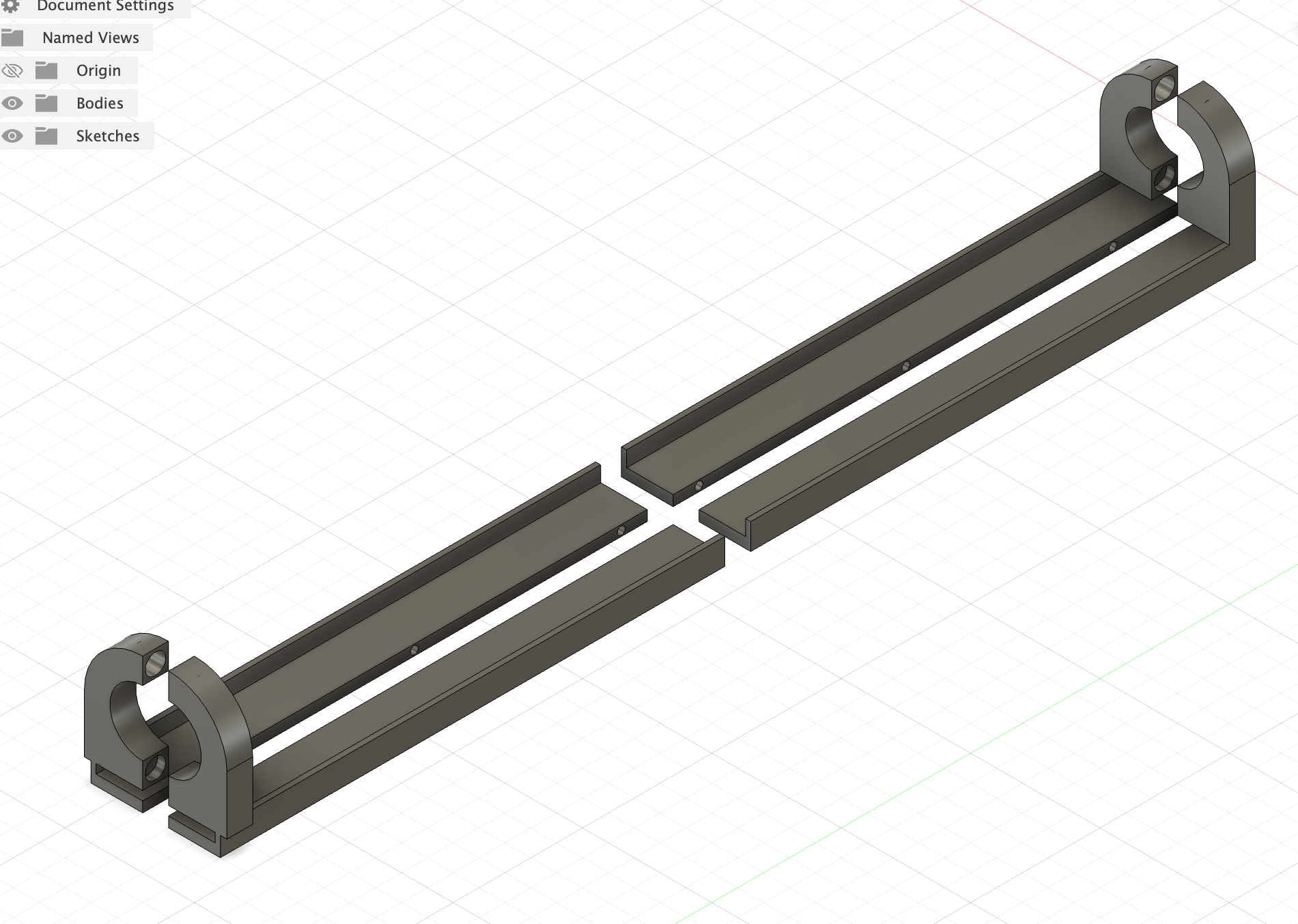
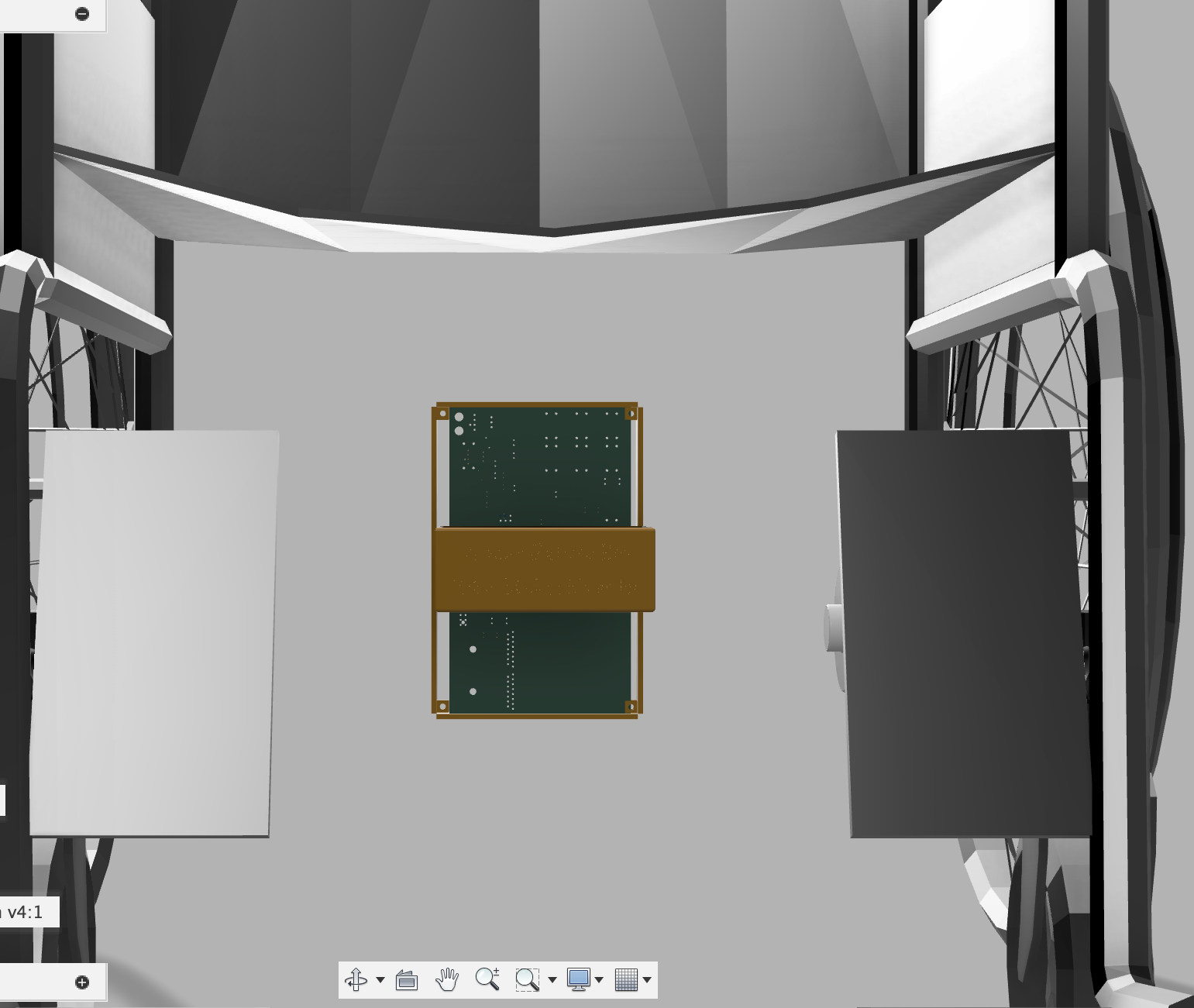
 ## PCB Protection (elevated so I can cool it easily and also connect heatsinks and thermal pads and stuff. ALso the walls are connected with straps to legs of wheelchair)
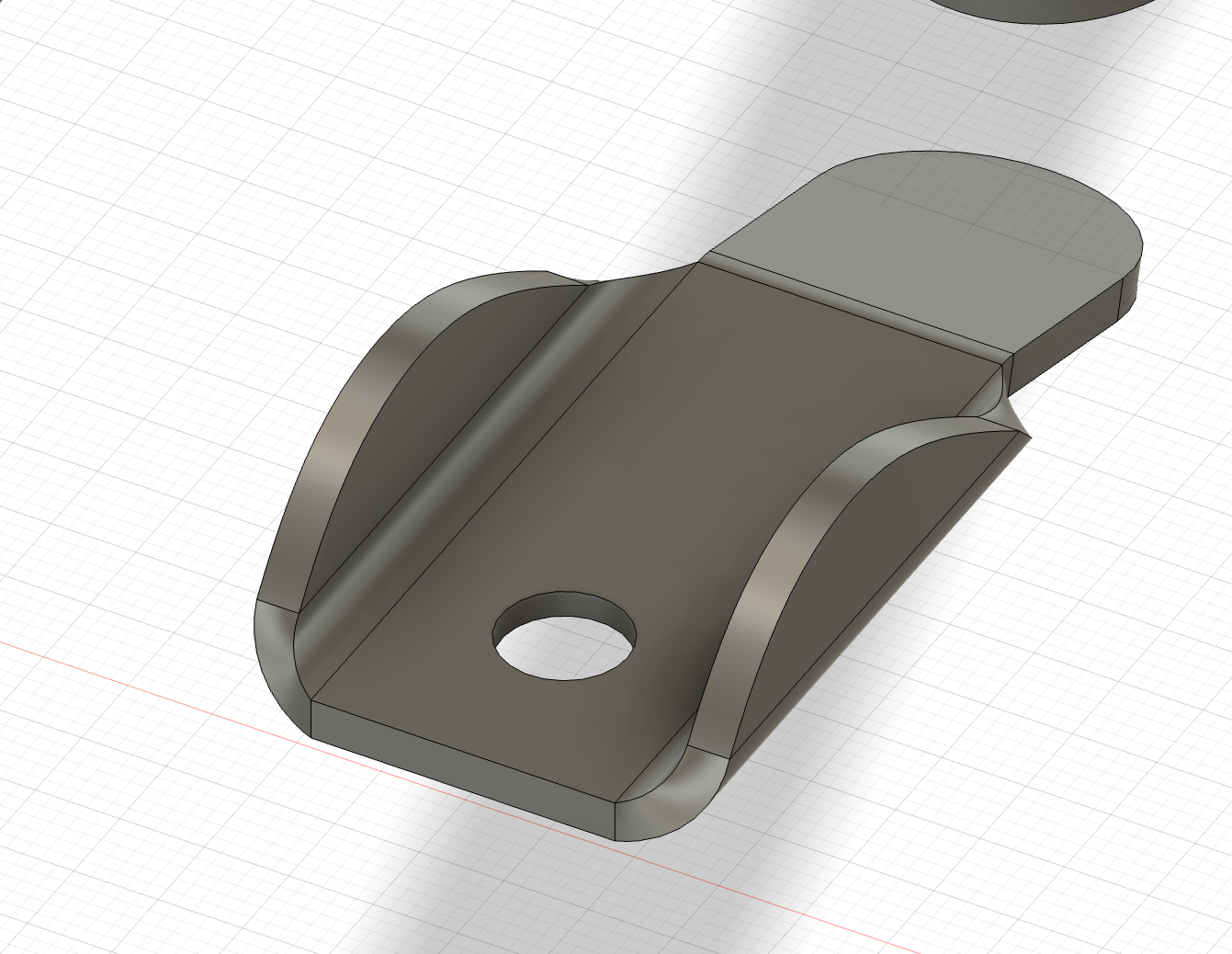
 ## Close-up of Lock Mechanism (will superglue spring and magnet)
 ## Wire Support on Armrest
🗓️ August 6 - 4 hrs
- modeled the whole wheelchair in cad using real measurements. main frame is welded steel tube construction, seat dimensions are 18
wide by 16
deep, backrest is 18" tall. integrated the battery box under the seat - had to adjust dimensions to clear the cross braces and leave room for user's legs. - pcb housing mounts to the frame behind the seat where its protected but still accessible. used aluminum angle brackets to attach to the frame tubes. housing is positioned so all the connectors face outward for easy cable access.
- added space for extra buck converter module on the pcb for voltage flexibility. thinking i might need 9v or 15v for some sensors later so having an empty module slot is good future proofing.
- changed some connectors from molex to screw terminals for easier field connections. also switched some headers from through-hole to surface mount to save space. used pogo pin connectors for programming headers so they dont take up permanent board space.
- updated the 3d models to match the real wheelchair measurements. had to adjust battery box height to clear the seat cushion and make the cable routing work properly.
 ## Control Panel and Wiring through Armrest
 ## Walker Handle and Lock Mechanism (my actual wheelchair can pull down the backrest)
 ## PCB Walls and Battery Box will be connected via straps to the 4 bars of the wheelchair legs
🗓️ August 7-9 - 10 hrs
- learned about thermal management for pcbs. thermal vias are basically small holes filled with copper that transfer heat from hot components on top of the board down to the ground plane for heat spreading. added thermal vias under the atmega2560, voltage regulators, and motor driver connectors.
- set up net classes in kicad to automatically manage trace widths. power nets get thick traces (1-2mm), high speed signals get controlled impedance (0.15mm with specific spacing), and regular io gets standard 0.1mm traces. this makes routing much more consistent and professional looking.
- copper pours are basically large areas of copper connected to specific nets. used copper pours for the main voltage rails and ground. 24v pour covers most of the top layer around the power section, 12v pour covers the motor driver area, 5v pour covers the logic section, and ground pour covers the entire bottom layer.
- made all high current traces as wide as possible - 2mm for motor outputs, 1.5mm for main power rails, 1mm for buck converter inputs. where traces couldnt be wide enough i overlaid copper pours to carry the extra current and spread heat.
- rerouted major power and ground connections to pass design rule checks with no errors. kicad checks for things like minimum trace width, via sizes, drill holes, copper clearances, and electrical rule violations. took several iterations to get everything clean.
- planned passive cooling strategy using the open pcb housing design. hot components like voltage regulators and the atmega2560 are positioned near the housing openings where airflow can carry heat away. might add a small 12v fan later if needed but trying to avoid the noise and complexity for now.
- added temperature monitoring with thermistors near the hottest components so the software can throttle performance or shut down if things get too hot.
🗓️ August 10 - 2 hrs
- finished applying copper pours - 12v on front layer and 24v on back layer. double checked that pours dont create shorts and respect all the net boundaries.
- updated project files and made renders of the final design.