Jug
A 6x3 column staggard split keyboard with a large thumb cluster.
Jug -- Split Keyboard
June 20: Made KLE and printed a test plate
This project I started a while ago for hackboard, but I redid the entire thing several times and never finished. I'm restarting from scratch again and today I made an approximate keyboard layout and printed out a plate to see how the layout felt.


When I was making it for hackboard I had originally thought I would make a 4x6 board with a medium sized thumb cluster (4 keys and changed to 5 later) but I'm now going to make it with 6 thumb keys and the main part will be 3x6 instead.
The first plate I printed as a test (from hackboard) looked like this (I hadn't finished the thumb cluster layout):

But this is the one I printed out today:


After printing it out and looking at the layout, I also decided I won't include an encoder because it sticks up way too much. I will probably put the interconnect where the encoder is. (I was going to use 4p4c but the connectors look kind of large. Maybe USB A. I have found double sided USB A cables on aliexpress and that shouldn't be confusing because only host should have USB A so it should be clear that it is for a different purpose.)
The stagger from hte middle finger to pointer finger and ring finger to pinky finger is a bit too large so I will reduce it a bit. I also found that the farthest out key on the thumb cluster is rather hard to reach so I might remove that as well. It should make the keyboard more compact which will be nice.
Here is a comparison between the new keyboard and my Lily58:

I also spent a bunch of time troubleshooting why Fusion wouldn't export and it seems like it was because my virtual machine wasn't able to fully connect to the internet because something was wrong with the DNS. I just changed it to cloudflare in Windows and it seems be fixed.
I'm not fully set on my keyboard's name but I think jug makes sense because it looks kind of like a jug/pitcher with a long spout like this:

Total time spent: 5hr
June 28: Modified KLE + redesigned plate
Today I modified the KLE to change the key stagger, removed one thumb key, and redid the thumb row. I moved the whole thumb cluster about 1/2 keys over. I changed all of the thumb keys to be 1u (I had one key that would be 1.25 before). I also removed the spot for the encoder and made a small recess so I could put the rp2040 pro micro and see how the spacing would be.


I then did a test print to feel the spacing of the keys. The main part of the keyboard feels good now. The part of the thumb cluster that is under the main part of the board is pretty good but the thumb keys that are farthest out I think would be better if it was rotated more.
Total time spent: 4hr
June 28-second: adjusted thumb cluster + first pcb design
I adjusted the thumb cluster by rotating the end keys more so that they are angled like the big key on the lily58. The layout feels really good now. I next started working on the pcb layout. I did the main layout but I'm not sure yet if I want to use RGB or not. I think I'll probably at least add a few leds for caps lock/num lock. I also printed out 2 1.5u keys to see how they look and I'll be using that in my design.

After doing the test print (the placement is good) I started working on the pcb. I made the whole pcb for the left side.

Total time spent: 3hr
June 29: Made reversible footprint for plated hotswap + work on pcb
I decided I want to make the pcb reversible so I made a footprint for hotswap sockets that can also be used to solder the switches in place. It is based on the plated ScottoKeebs footprints but should work flipped as well. I also decided I won't add rgb because routing would be especially annoying with the reversible footprints taking up so much extra space.

I also made a diode footprint with the silkscreen on both sides and the model showing on both sides.

After making the footprints I redid the pcb again. I was a bit confused about how the reversible footprint I found for the mcu works but it seems like you just solder the jumpers on the side that the mcu faces. (the side that the side of the mcu with the components faces.)

There were some errors on the mcu footprint but I think that it is just because the jumpers have a gap between them that doesn't have solder mask and it thinks it will cause a short. I can't figure out how to get rid of the errors but it should be fine.
Total time spent: 5hr
June 29: Made USB A interconnect reversible
I had forgotten that I wouldn't be able to reverse the USB A connector for the interconnect so I spent a while fixing that. I used the same method with solder jumpers as for the mcu and it was really confusing. As I understand it this should work to make rotating the connector (flipping the side of the board it is on) work.
After figuring out that I also added holes for standoffs to pass through to support the plate.
Total time spent: 4hr
July 1: Added indicator leds and worked on firmware
Today I added indicator leds. They are small 1206 smd leds so that hey can fit under the plate and diffuse through. There will be two leds per side (one red and one blue). One on each side will be an indicator for either caps lock or num lock and the other will be to indicate whether i'm in the colemak or qwerty layer.

Yesterday I was working on my case but Fusion crashed and I lost all of my progress because the internet had just gone out.
The other thing I did today was work on firmware. I did all of my layers and am almost done. I will be adding vial support later but I'll do that after finishing the basic firmware.
Total time spent: 5hr
July 1: Worked on firmware + added silkscreen to pcb
I added my logo + text to show which side to solder the jumpers for the mcu. I also learned that AliExpress won't ship to me anymore so I have switched from the RP2040 Pro Micro to the RP 2040 Zero. I made a reversible footprint for the MCU since I couldn't find one online.

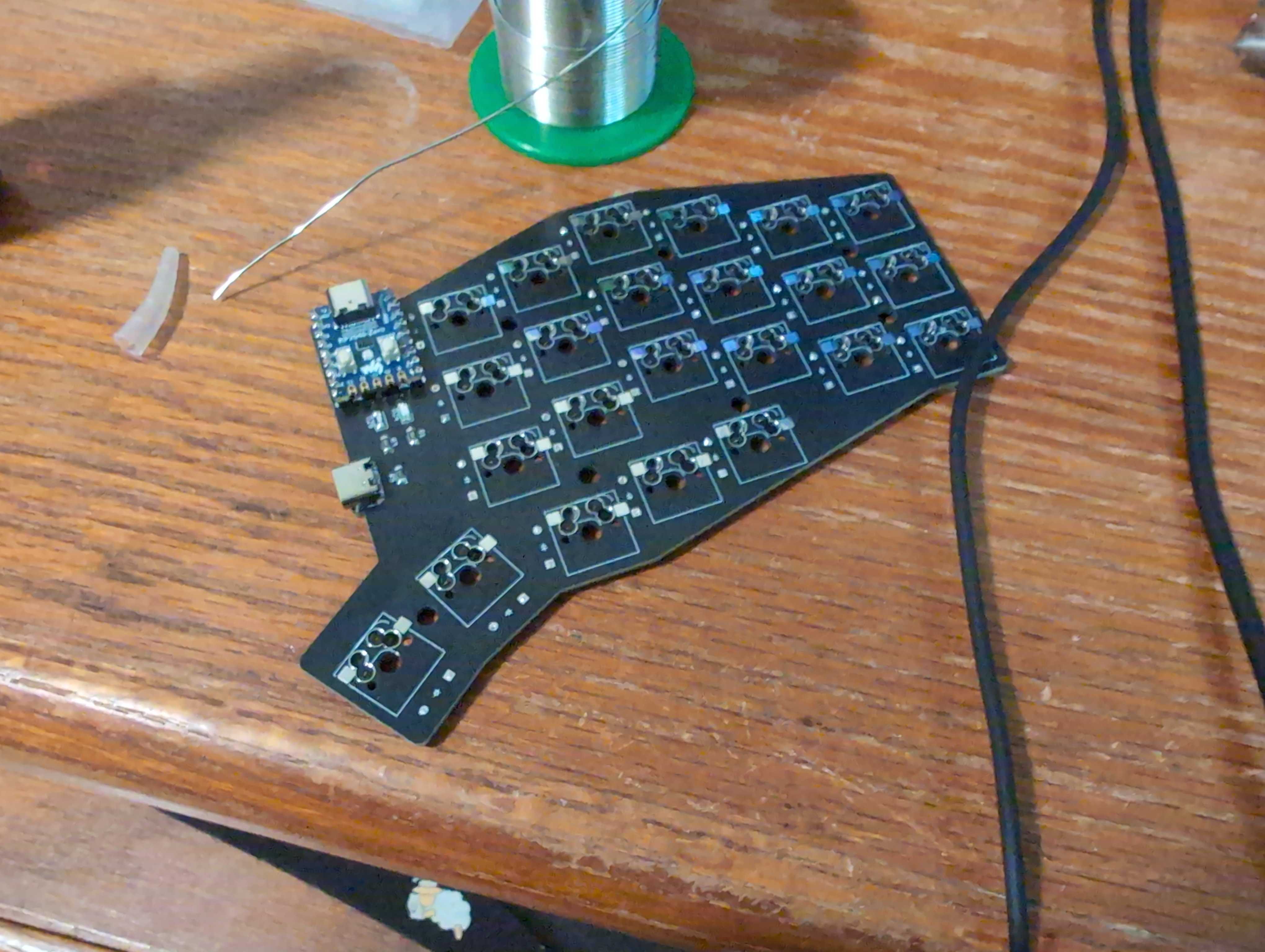
I then had to re route part of the pcb after swapping out the footprint and then did a check over the whole thing. I added some silkscreen logo and text (to show which side to solder/place components on). This is (for real this time) the final version of the pcb:


Total time spent: 6hr
July 3: Switched interconnect to USB C and worked on case
I decided that I would switch to use USB C for the interconnect because USB A-A cables aren't as common. They can be found on Amazon but basically everyone will have a USB C-C cable.


I worked on the case and finished almost the entire thing.
I forgot to get any pictures of the case.
Total time spent: 5hr
July 4: Finished the case + QMK firmware
I finished working on the case. Because the pcb is reversible with the components staying in the exact same position, the right side will just be a mirror version of the case.

I added a recess in the plate above the indicator leds that should make them brighter in just that area and hopefully it will look nicer.

I also worked on my base QMK firmware and was able to compile the basic version that doesn't have combos or extra features.
Total time spent: 5hr
July 5: Worked on Vial firmware
I finished the Vial firmware and was able to flash it on another RP2040 board that I have and was able to short the pins to print out the keys on the left half. I also got vial itself working. I struggled a bunch because apparently the ordering of the matrix definitions really matters so all of the keys were mixed up.

Total time spent: 4hr
July 6: Worked on README and full parts list
Added all info to README and finished selecting parts.
Total time spent: 4hr
July 23: Stuff arrived and started soldering.
All of my stuff arrived (other than a few keycaps which I can print myself). I started soldering the keyboard and finished one half. Everything seems to work quite well.

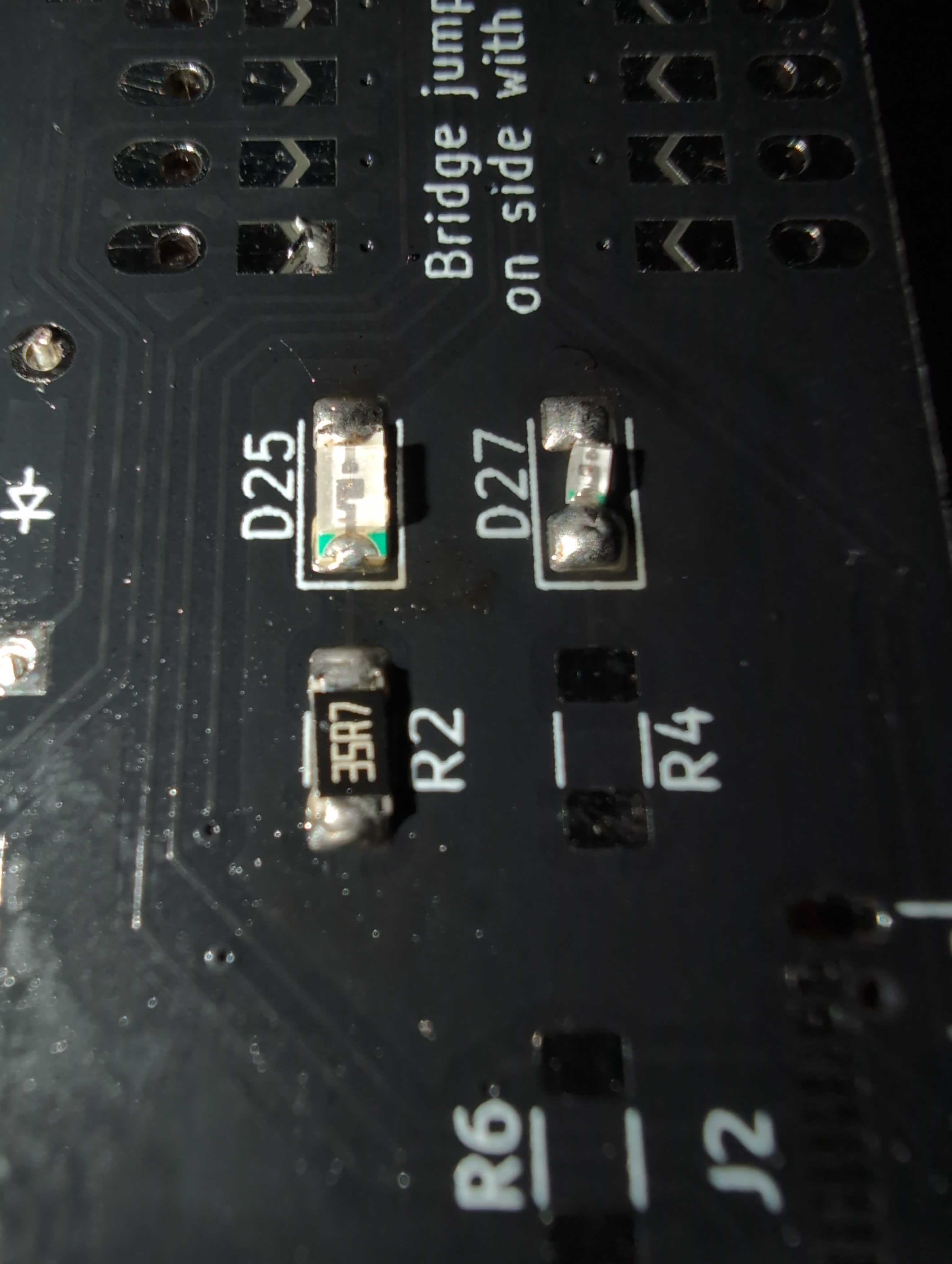
I accidentally ordered 0603 red leds instead of 1206 so they are the wrong size for the footprint but I was still able to solder it in place with a big glob of solder.

Total time spent: 3hr
July 24: Soldered second half
Today I soldered the second half of the pcb. The reversible footprints all worked perfectly but after connecting the halves the second side wouldn't do anything. By itself it is able to type when directly connected to the computer but the USB C interconnect doesn't work. I tested with a multimeter and it seems like there is power on the second half and there is a connection between the two interconnect pins (between the halves) but it seems like there is some resistance on the interconnect line because I chose to use D+ which I think has some kind of active filtering or something?
Total time spent: 4hr
July 25: Fixed interconnect
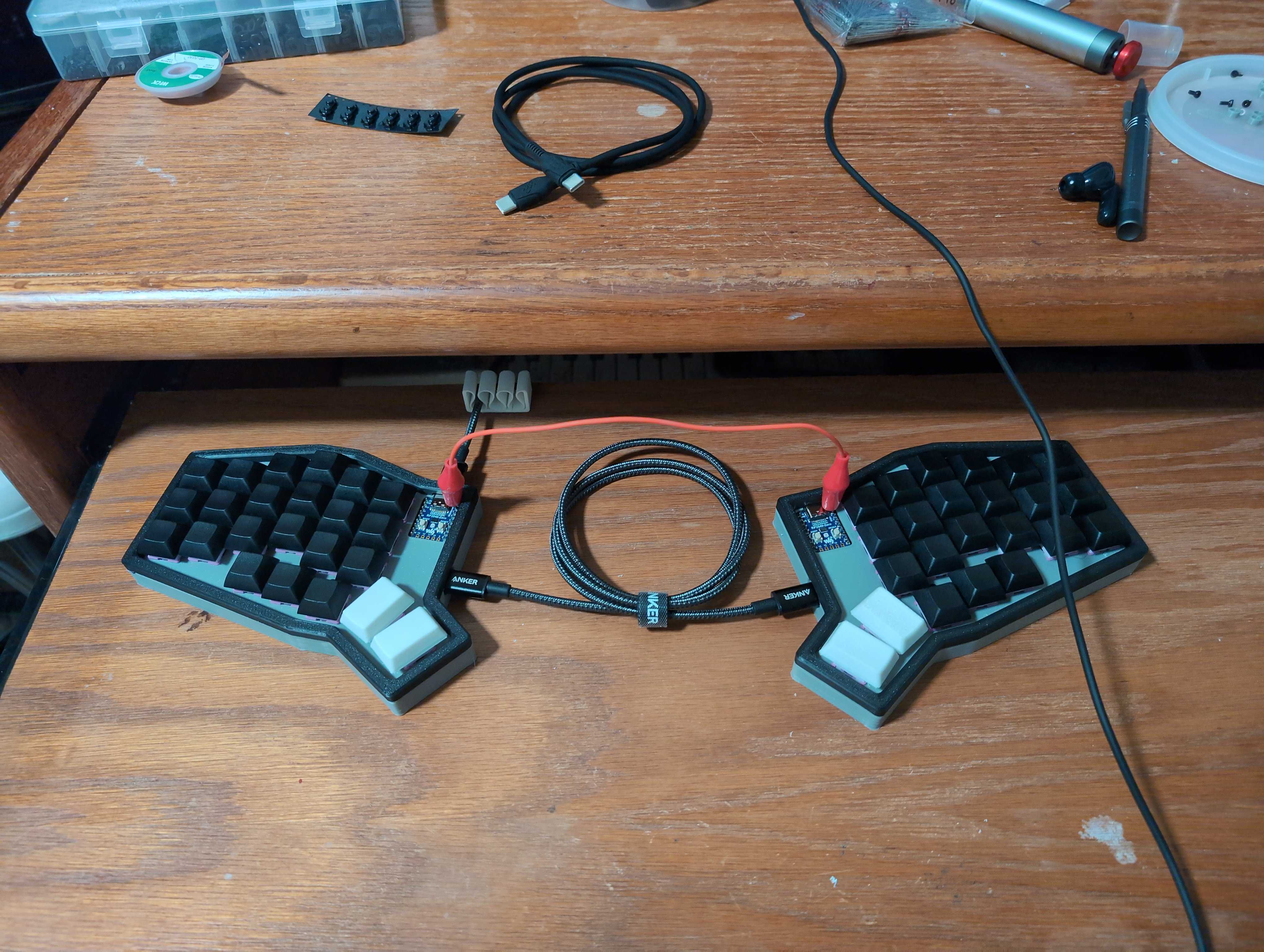
I did some testing and managed to get the halves to connect. I used a alligator clip jumper wire to connect the interconnect pins and the keyboard worked. For a few seconds it also worked over just USB C but it stopped working and that hasn't happened again.

I then melted a hole in the side of the case and soldered some wire on to each interconnect pin and brought the wire out the side. I crimped DuPont connectors on to each one so that I can change the length of the wire in the middle if I want.
Total time spent: 2hr
