
Led Controller PCB
An ESP32-C3 based LED controller PCB for Home Assistant.
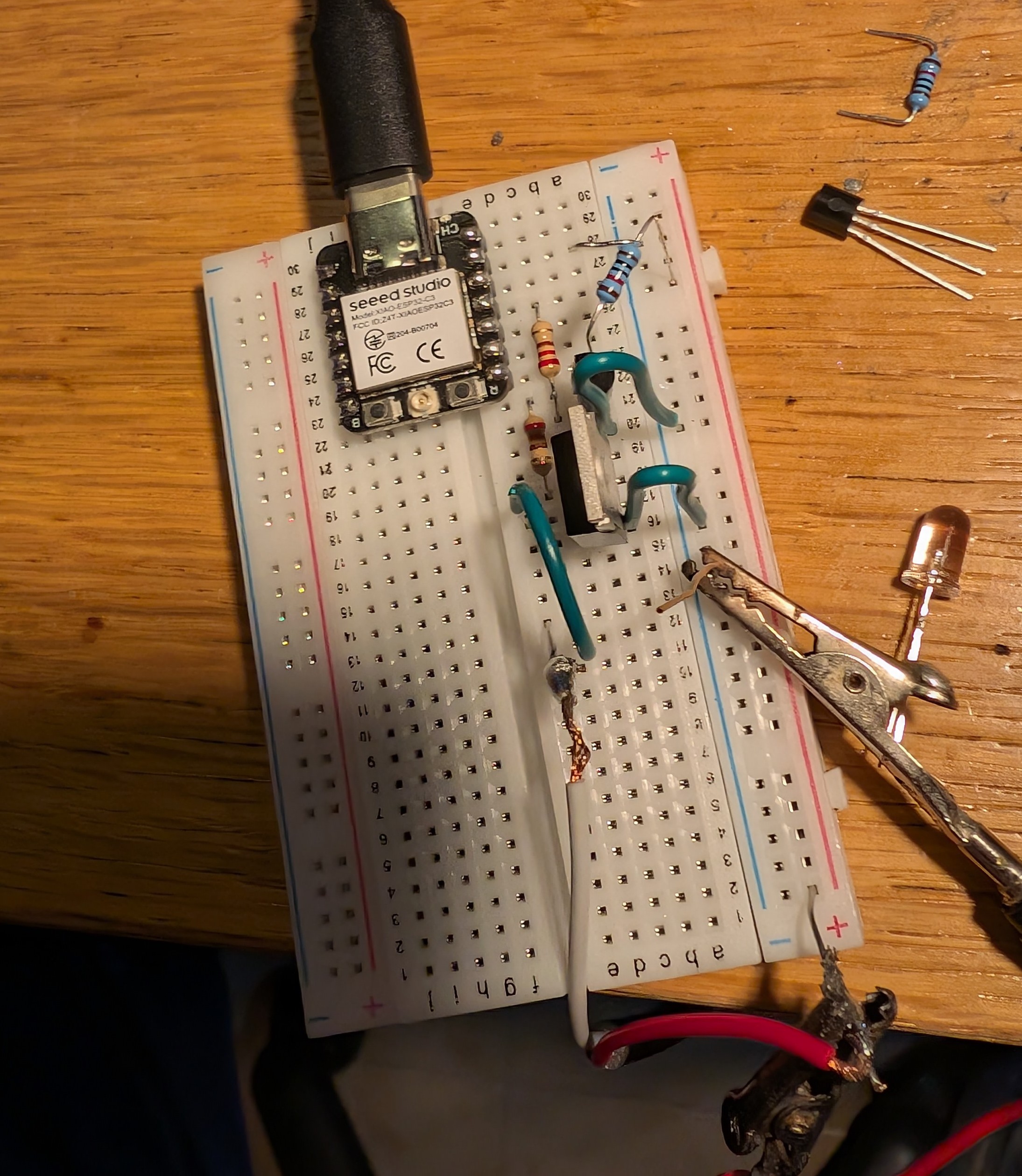
May 16th: Did a protoboard prototype!
I wanted to test if the idea I had would work, so I made a prototype on a protoboard.
First, I used a XIAO ESP32C3, a few resistors and a Power Mosfet IRLZ34N. The leds didn't completely work, but I found out it was because I wasn't fully saturating the mosfet.
To fix it, I use a BS170 to drive the IRLZ34N. I'm not sure if the BS170 fully saturates. That's why I connected it to 24V (input) so it would saturate the IRLZ34N.
Total time spent: 6h
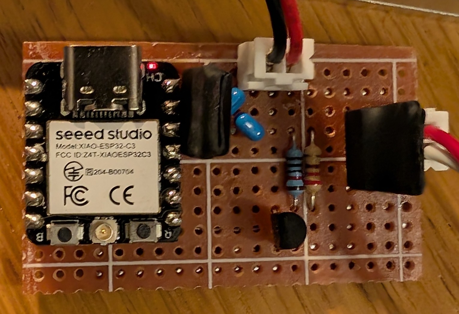
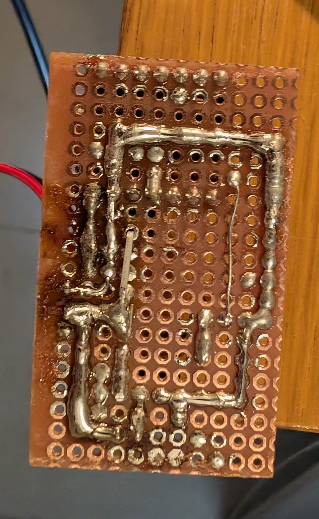
May 17th: Convert the design to perfboard
I now had a working prototype, so I wanted to convert it to a perfboard design.
I used KiCad to design the schematic so I would have a better overview of the connections. (I still messed up a few connections, but I fixed them later.)
I added a few extra components, like a 5V regulator so I could power the ESP32C3 from the 24V input, and a few capacitors to filter the power supply.
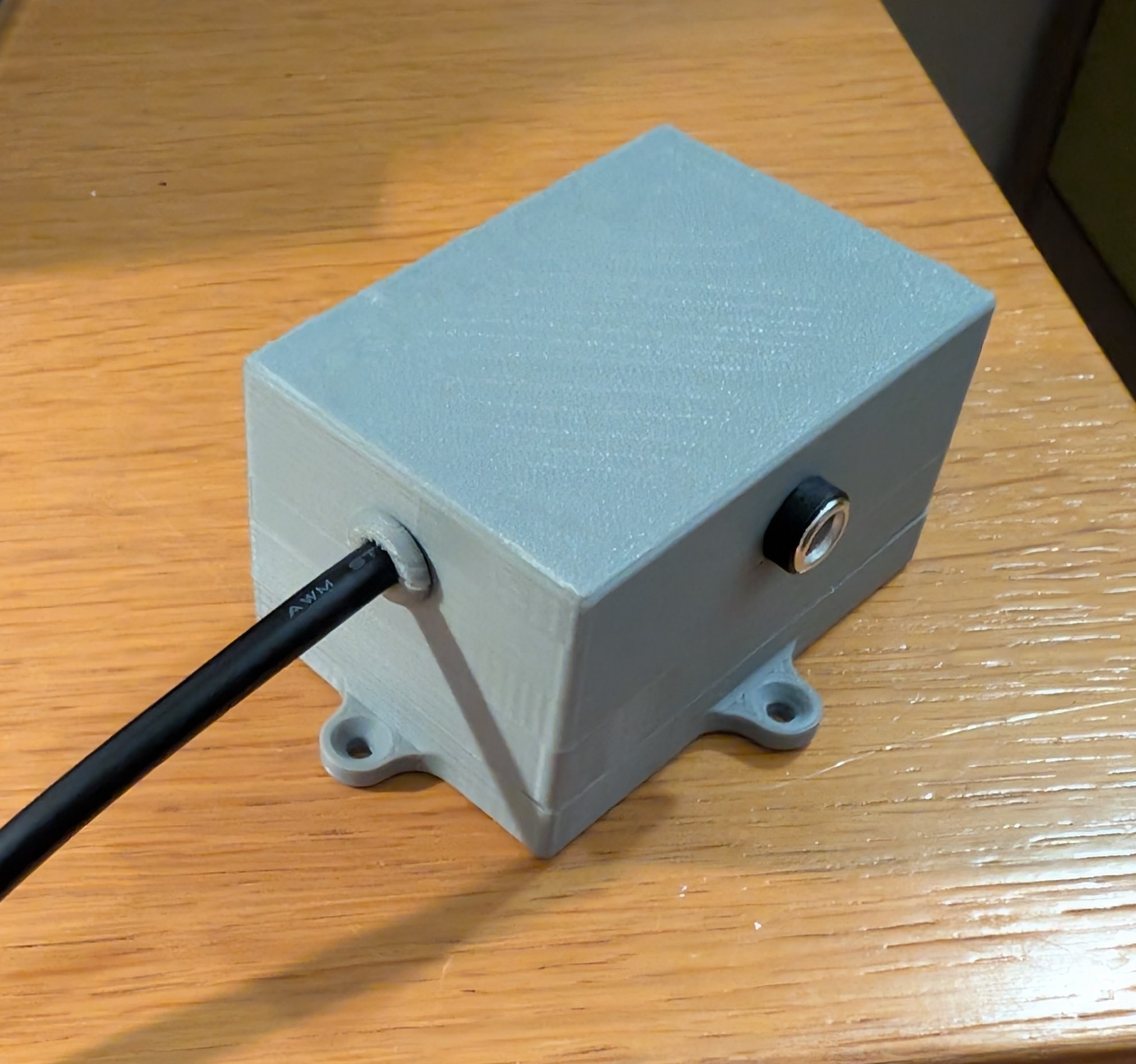
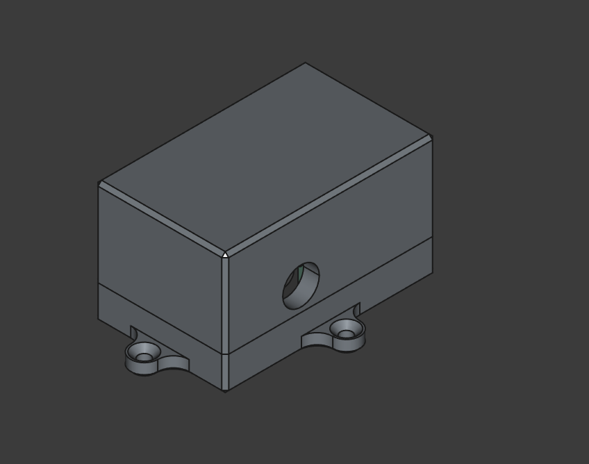
I also designed a case for the perfboard, so I could start using it.
Total time spent: 10h
May 18th: Did a PCB!
Now I had everything I needed to start my PCB design.
I used KiCad to design the PCB, reusing most of the schematic I used with the perfboard. I did most of the components THT so they would be easier to solder.
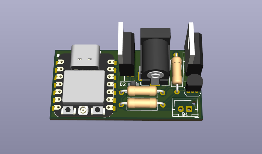
I had to also redesign part of the case so it would fit the PCB.
Total time spent: 6h
August 6th: Building the project
Today I built the project. I had to solder the components and assemble the case, but it was quite easy and quick. I used a 24V power supply I had lying around and connected it to the pcb. The only problem I had was that I couldn't find the barrel jack connectors I ordered, so I used a JST one instead.
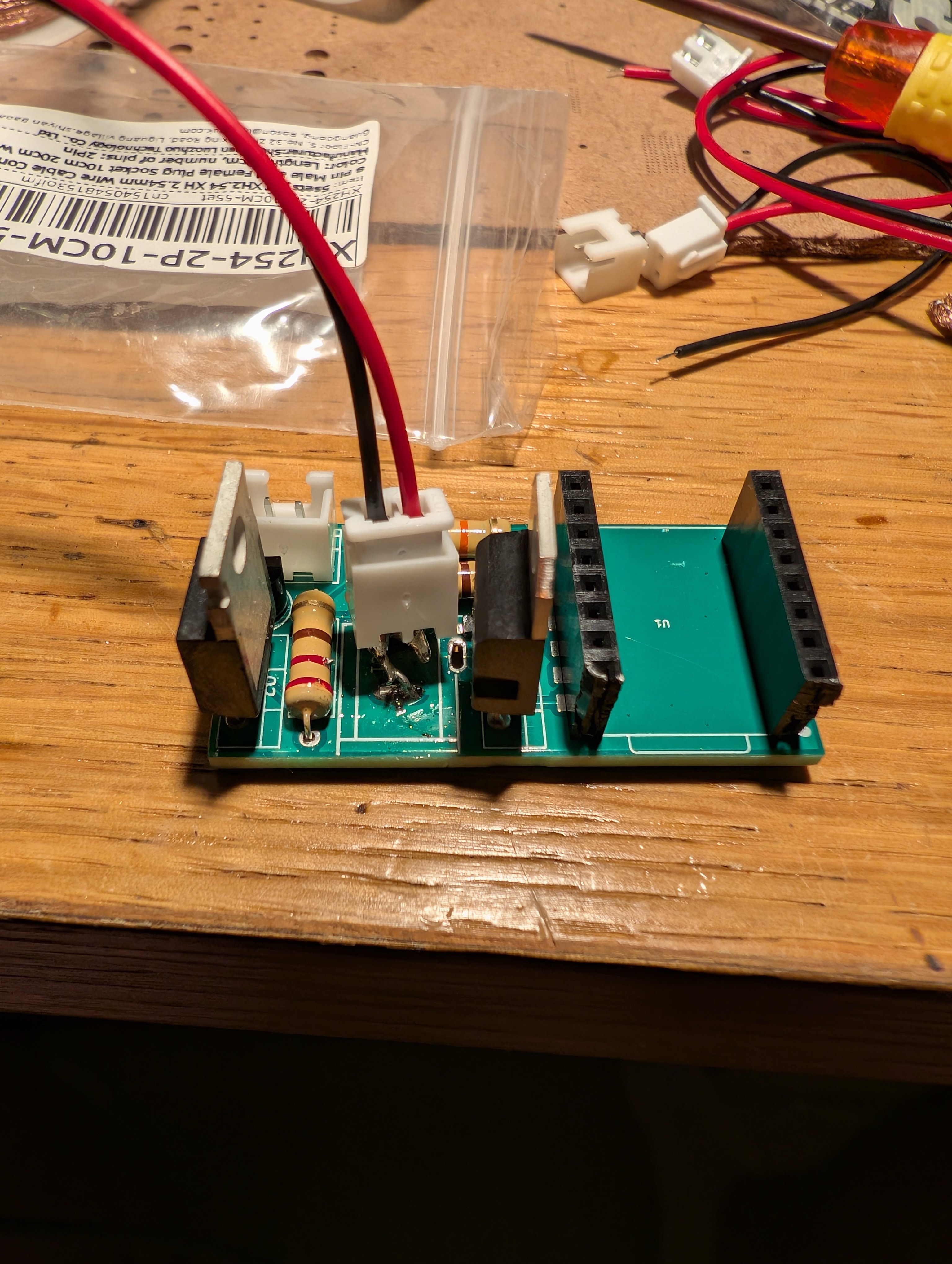
Total time spent: 1h