
Fm Transmitter
USB FM Transmitter
Some images in this journal are unavailable due to a CDN issue, and I don’t have backups. This only affects older entries and does not impact the main project files or build instructions.
What am I making?
My plan is to make a small device that plugs into your phone or computer and then can stream audio from that computer over FM over a short distance (1-2 meters) essentially allowing you to create your own mini radio station. Devices like these already exist and are mainly used to stream songs from your own device over to the car radio. My goal with this project is to create something similar and make it as plug and play as possible.
Goals for this project
Low Cost PCB
Tiny USB Drive form factor
1-2 Meters of Range
Programmable (set frequency,gain etc)
Time Spent Overall: 48 Hours
May 20th - Initial Research
Well this project seems a lot simpler than I expect it to be, all I really have to do is stream audio from a DAC over to the FM TX Chip and that's basically it. In order to tune the TX chip's frequency and other parameters I need to send data over I2C to it, which I think would be better to just send those commands from off board (like from an arduino or any other mcu). As I'm aiming for a low cost there isn't really a need to have a mcu on board, especially not for version 1.
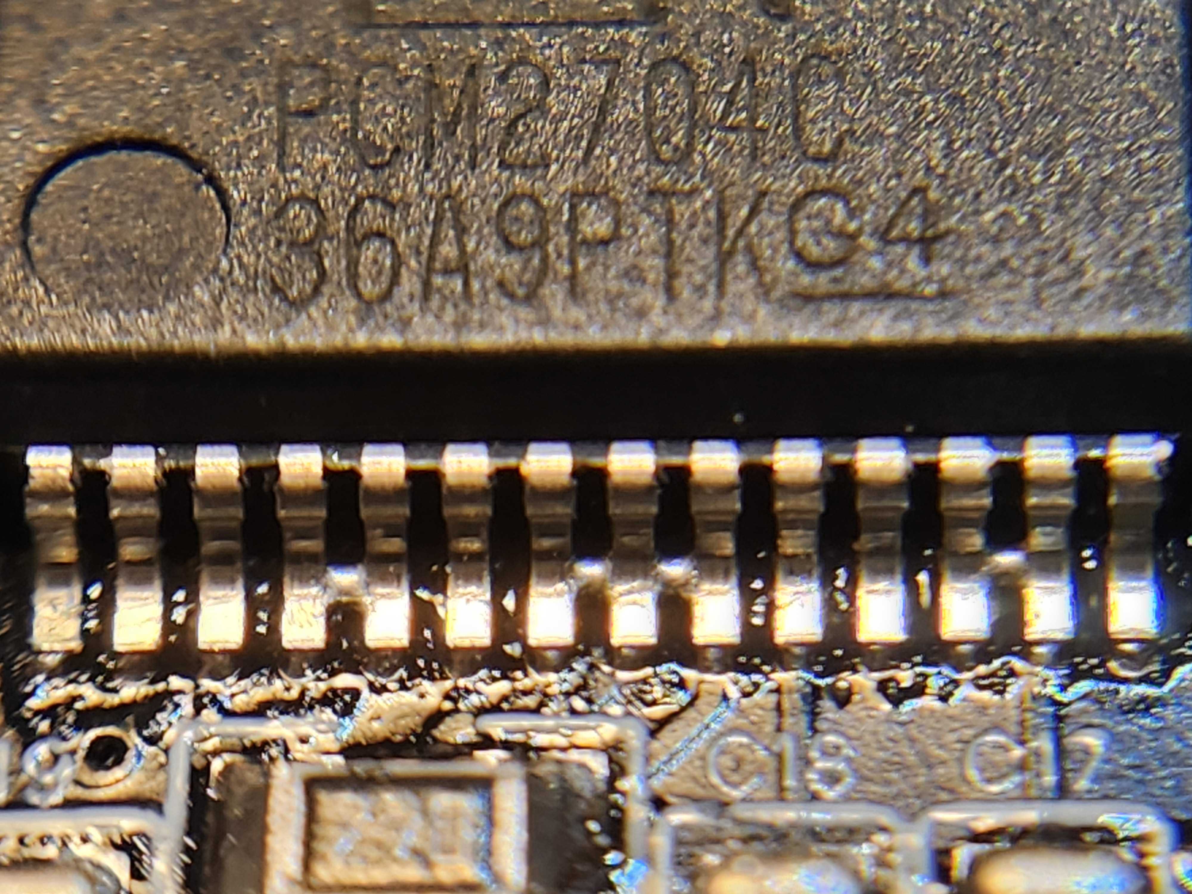
After a few hours of research and going through datasheet I decided to go with this stack- FM Transmitter: KT0803L This is an overall good chip, its a low power FM transmitter that takes in analog audio. It can be controlled by writing to its memory over I2C. USB Audio Chip: PCM2704C Acts as a USB audio device, has stereo analog output which can be used by our transmitter. No firmware needed
And well that's basically it for version 1. Just two little chips!!
My current plan is to have a really really basic version 1 with USB A, and then look at what I did right and what I did wrong. Then create version 2 with a mcu which can be programmed over usb, and look at what I did right and what I did wrong. And finally, for version 3 fix all the previous mistakes and add USB-C to it.
Time Spent: 2 Hours
May 21st - Schematic Finished
Today I printed out the datasheet for the KT0803L and the PCM2704C and read them and researched a bit more. I made a schematic for the TX chip using the example schematic provided in its datasheet. I did the almost the same thing for the PCM2704 Chip, but its example circuit sucked (you had to read the values from like a paragraph of text) but luckily somebody made a project using it so I follow that schematic. It was pretty much the same except you could actually see the component value in the schematic (link to that project).
NOOO, I just realized that the transmitter chip (KT0803L) is not in stock on jlcpcb or lcsc. Also I just uploaded my unfinished pcb to jlcpcb to get a rough estimate of how much it would cost and its a more than what I initially anticipated. It costs around around $60 CAD to get 2 PCBs assembled, which I feel like is way too expensive for such a simple project.
I think instead of getting them assembled from jlcpcb I'll solder them myself, this would be my first time ever reflow soldering a board. Its gonna be fun!!
Schematic that I made today-

Time Spent: 5 Hours
May 22 - PCB Design
Since I am now gonna be soldering the board on my own I decided to use 0805 footprint for the capacitors and resistors. I've also decided to now just source my parts from aliexpress, its more expensive that parts from jlcpcb but hey I'm saving a ton of money by not using PCBA.
Here are some changes I did in my design: - Changed the LDO, now using a MIC5205 - Added an ESD protection module on board - Changed up a lot of footprints - Now using a 12Mhz crystal for both the audio chip and USB chip
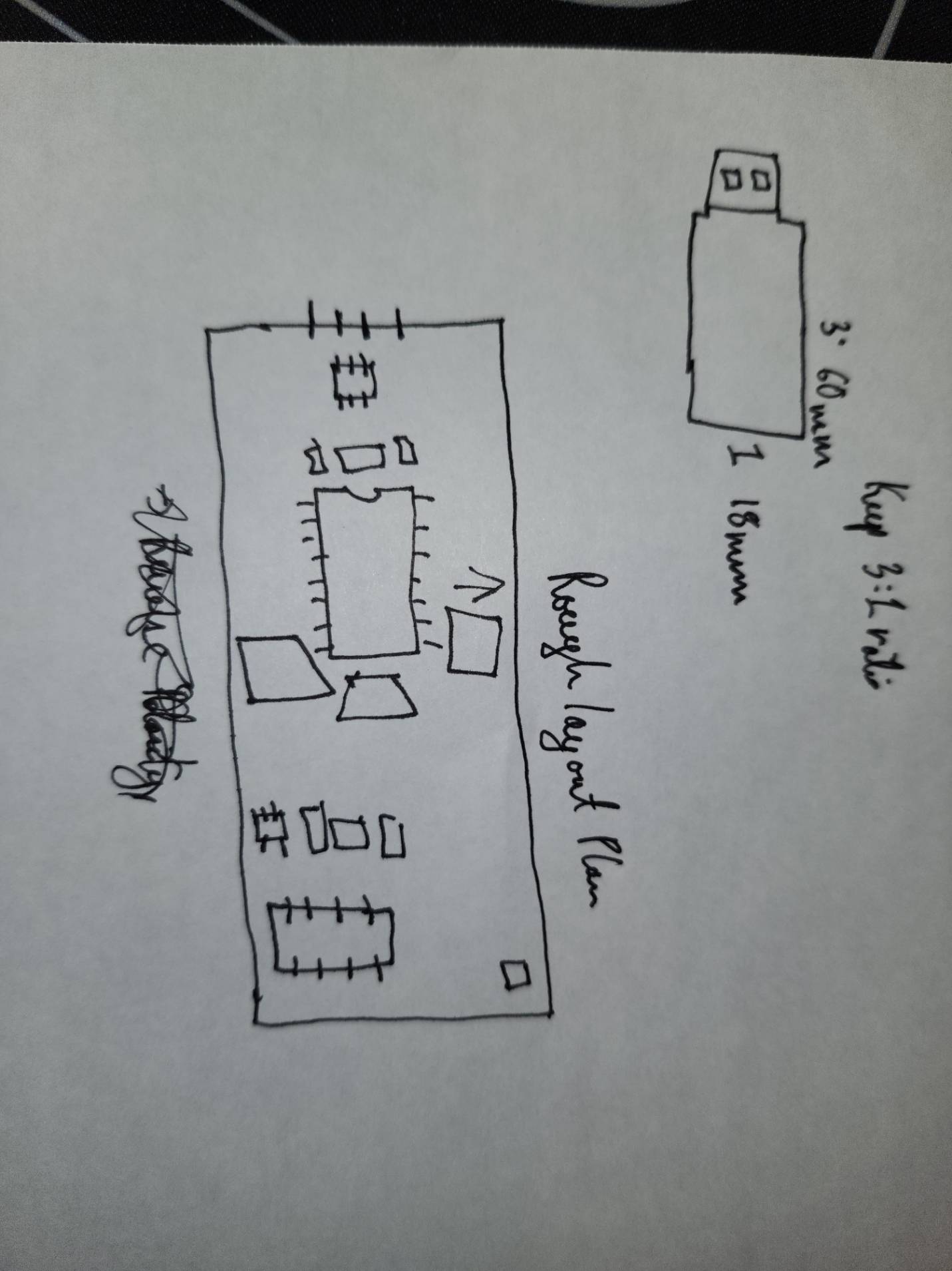
I made a rough PCB layout to sort of picture how I'm gonna place the components, and I did not like the layout I made


As you see in the images above its a pretty 'Chonky' board. Its not even that big its just Chonky and wide which I don't like. Plus there's a lot of empty space on the PCB which means the design can be compacted more. Which is exactly what I'm gonna do.
Time Spent: 5 Hours
May 23 - Finished Version 1!!
Making a rough PCB layout yesterday really helped me visualize how I was gonna fit everything together on a board. To actually figure out how my new layout should look like I drew a layout on paper (not to scale, just eyeballed the sizes)
After this I actually started on the new layout, It took quite a while to fit everything properly into a small board. Then after I was finally happy with the layout I started routing traces, the routing was very sketchy
is basically all I have to say.

3D Render of the PCB (The 3D models are a bit messed up and not the correct size)

Time Spent: 4 Hours
May 24 - BOM
I finished my final BOM today!! All the components and tools are gonna be ordered from aliexpress. My overall cost for this project is coming to be around 100 USD. Which I know is pretty expensive but a big portion for this is the PCB shipping price which is probably around 17% of the budget. I think I probably spent about 80% of the time today just on finding cheap parts from reputable sellers on aliexpress, I got most of my items for pretty cheap with free shipping. Only the main two chips (PCM2704 and KT0803L) had shipping fees, but It was not too overpriced so it was alright.
I also wrote a readme for the project today, formatted everything nicely, added source files in the main repo
Looking back at my initial goals I think I pretty much achieved everything I wanted except for the USB C part but its alright because soldering USB C would be practically impossible for me to do on my own and getting it fabricated would be super expensive.
Time Spent: 3 Hours
May 29 - Ordered Parts
Ordered all the components and the PCB today. I also realized that I put the wrong LDO in the BOM but I fixed it and made some minor little changes to the PCB (used 1uF caps for the LDO instead of 22uF).
June 12th - Failed build
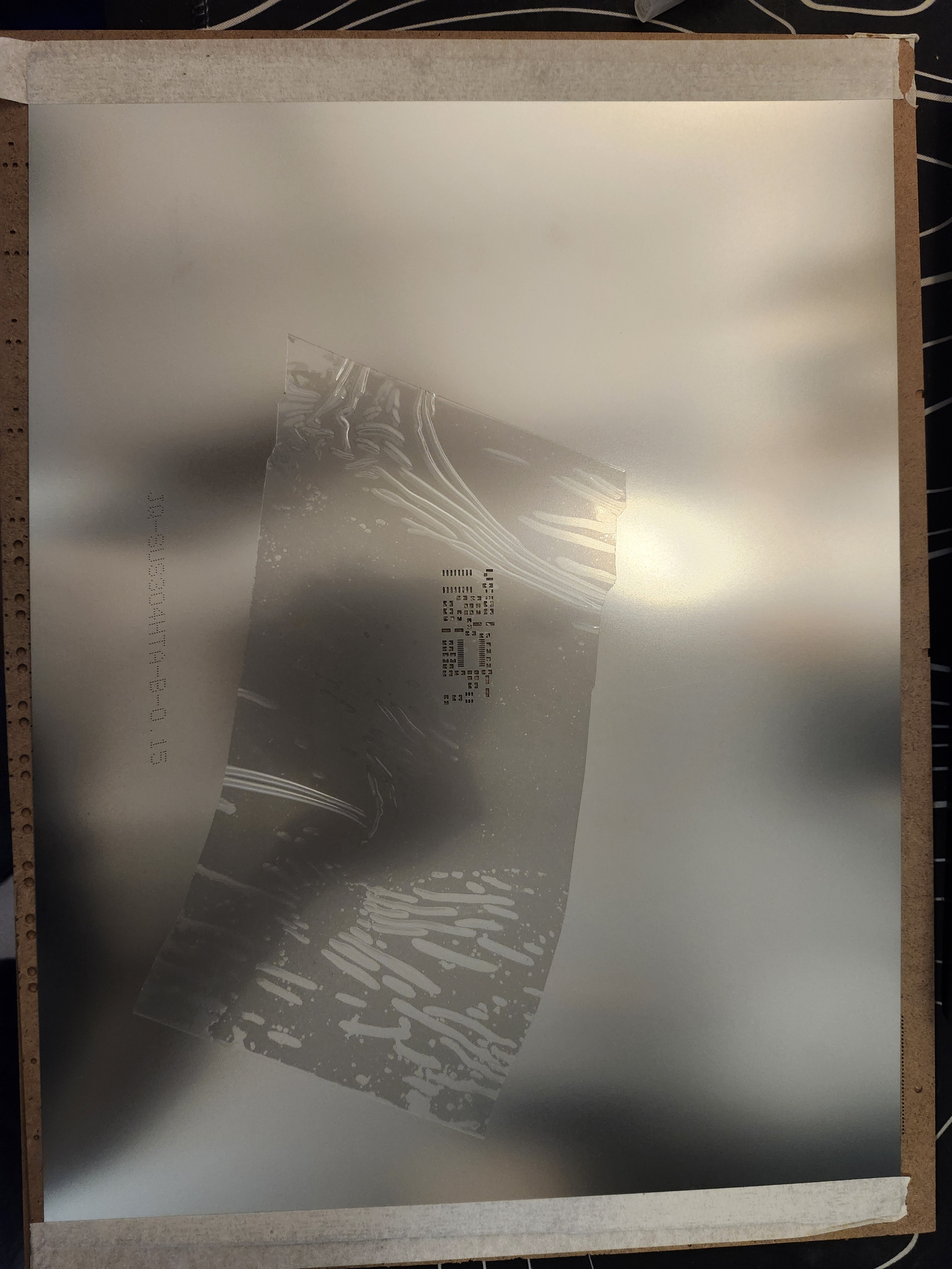
All my parts arrived last week and my PCB and stencil arrived today.
PRO TIP: when ordering a stencil set a custom size
I went with jlcpcb's default stencil size and didn't think anything about it until today when it finally arrived. :sob:
Big Ass Stencil
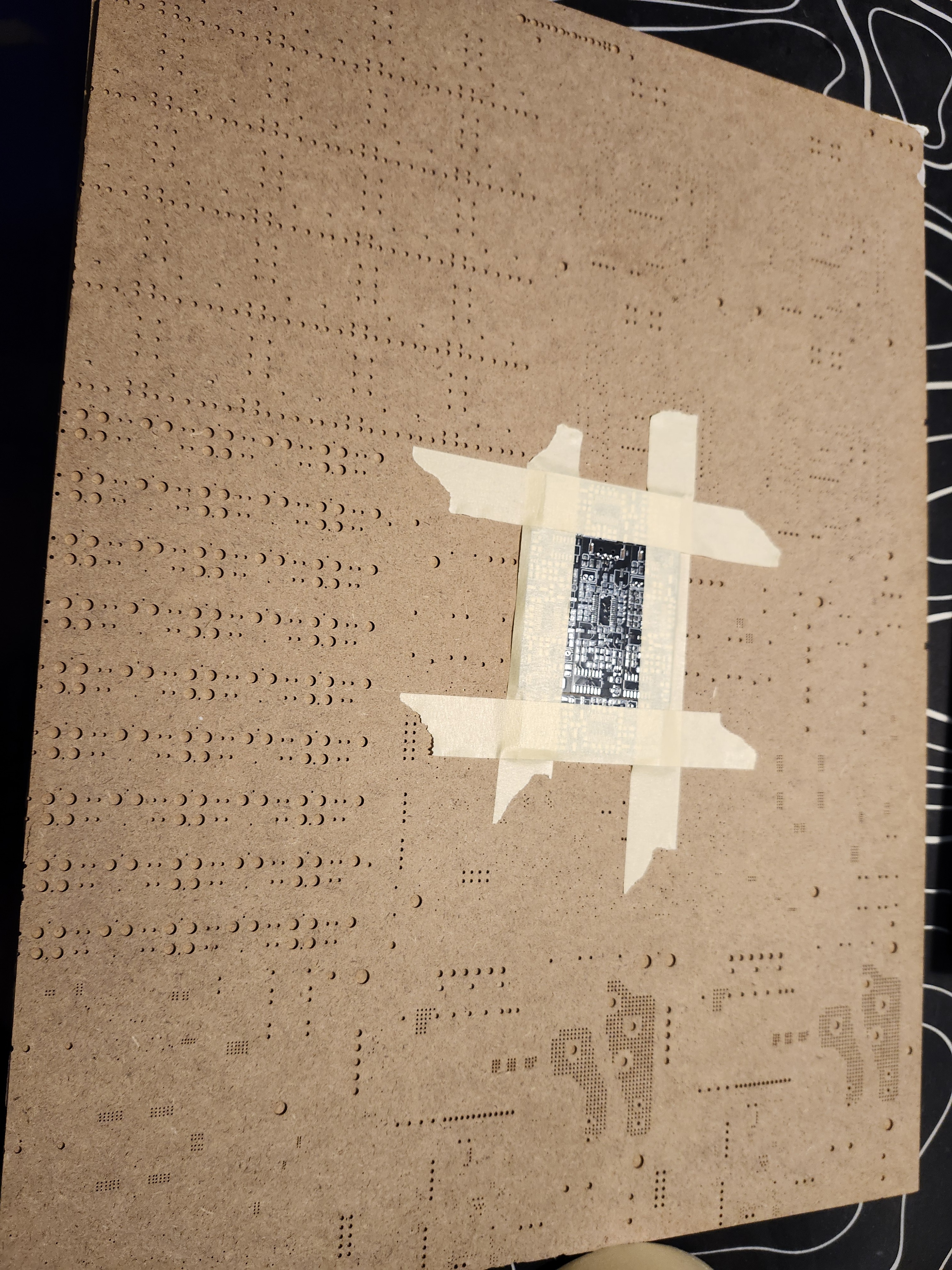
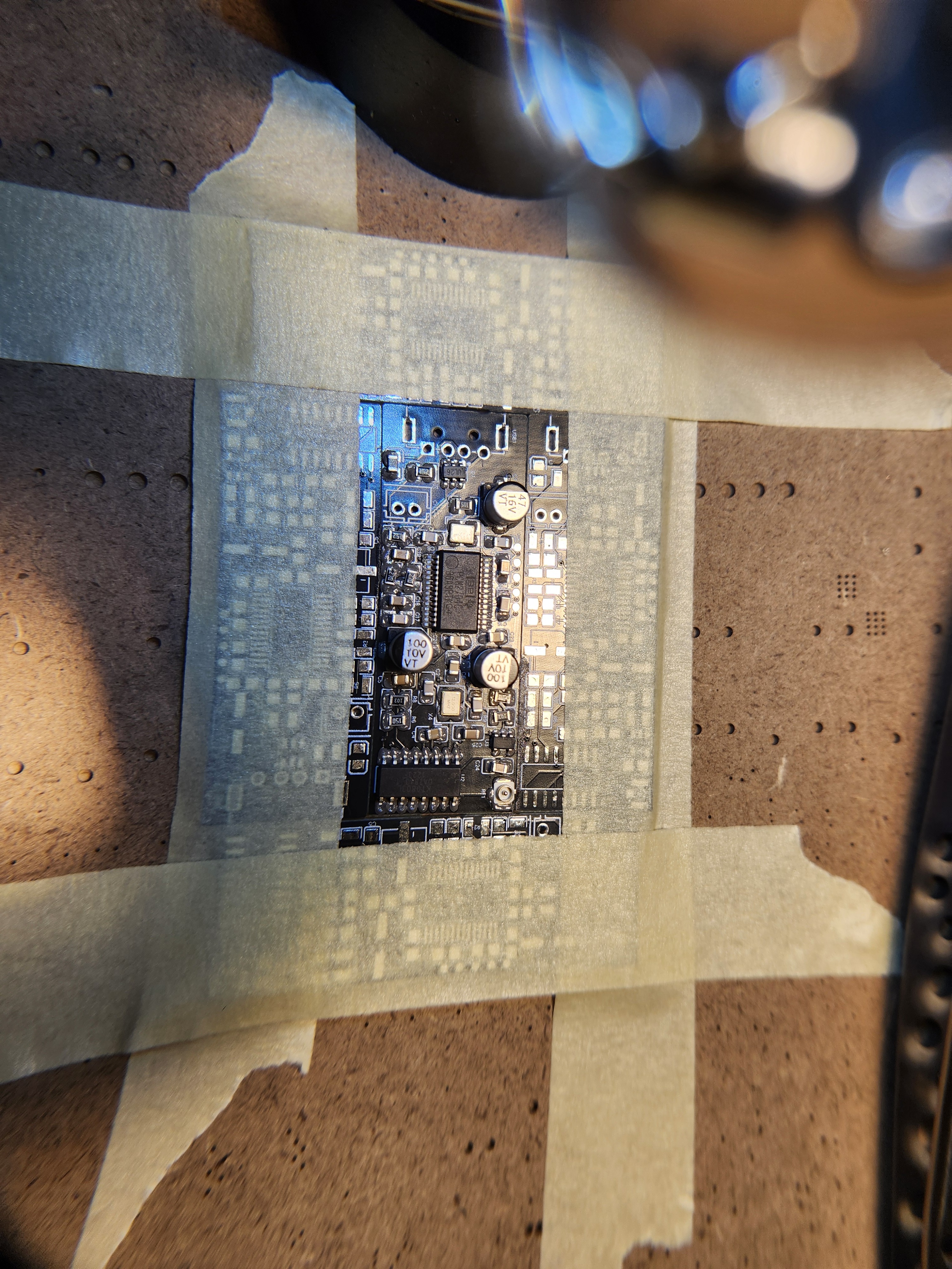
I setup my workspace and started placing the smd components on the PCB to get it ready for the hotplate.
Turns out the PCM chip was actually not connected to any power. I don't know how I even missed that but that really sucks :c. Also there were a lot of solder bridges on the PCM chip, it was SSOP package and the leads were superclose and a few of them bridged without me noticing. All in all I think I probably killed that chip, thankfully I anticipated that something like this would happen and I bought 2 PCM chip.
Solder Bridges on the PCM2704 Chip
Time Spent: 6 Hours
June 14 - Fixed PCB
I fixed up the PCB and connected the PCM chip to power and ordered the new boards
June 27 - It Works!!
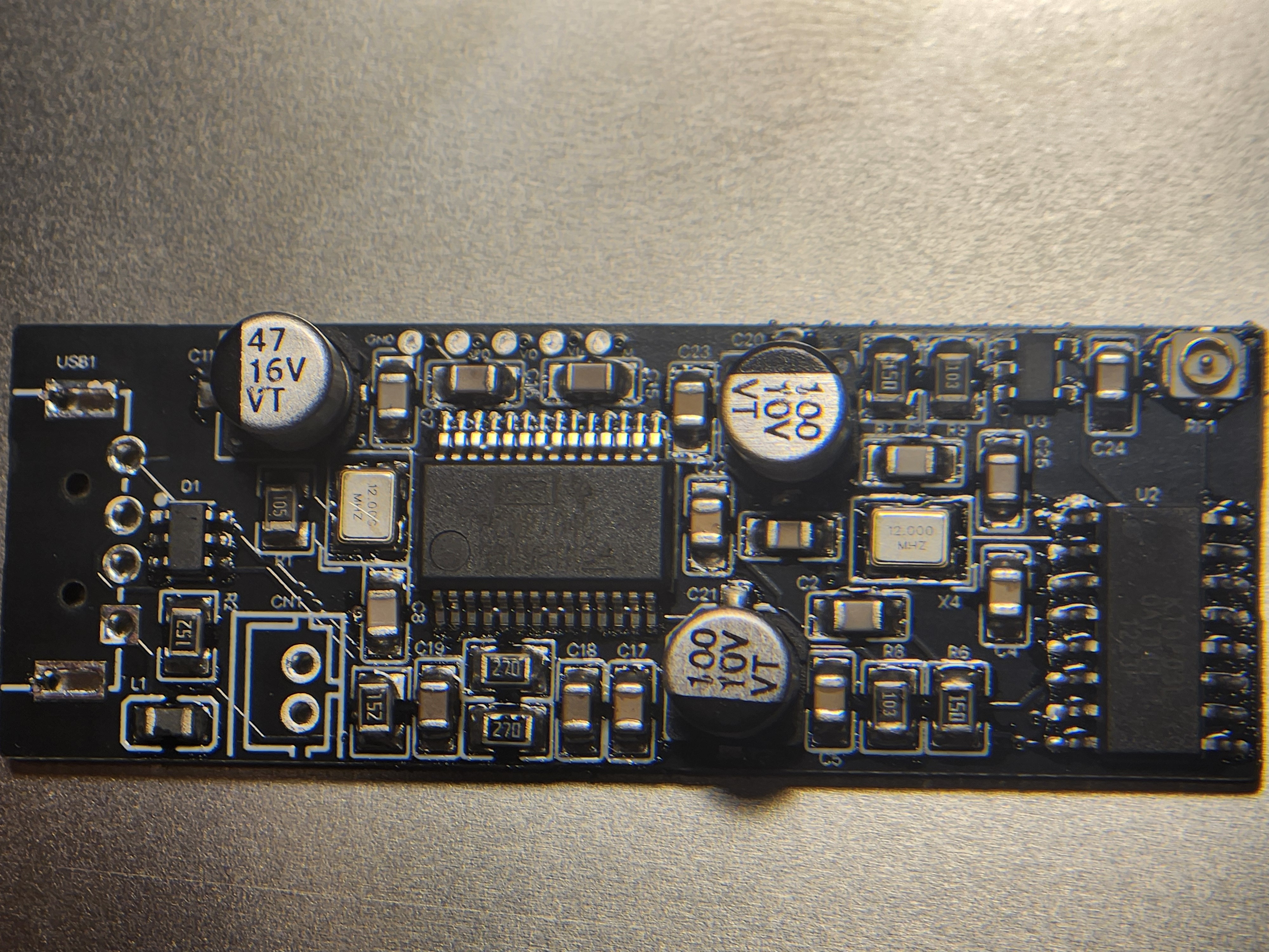
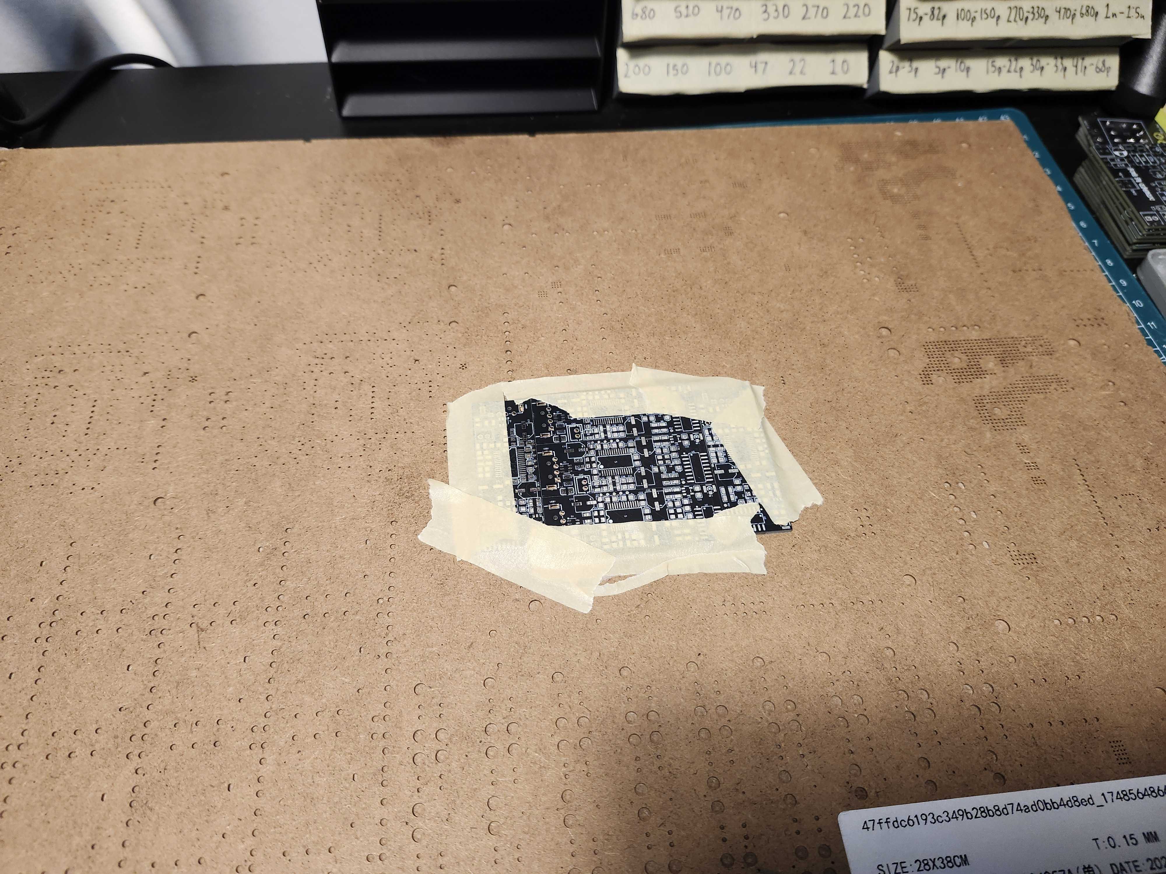
The updated PCBs arrived today at around 12. I spent about 3 hours soldering everything together, I probably spent about an hour just to apply the solder paste properly ( I had a big stencil so it kinda warps up and the paste gets smudged and squished almost). I also fixed up the remaining solder bridges with my pinecil.
New PCB
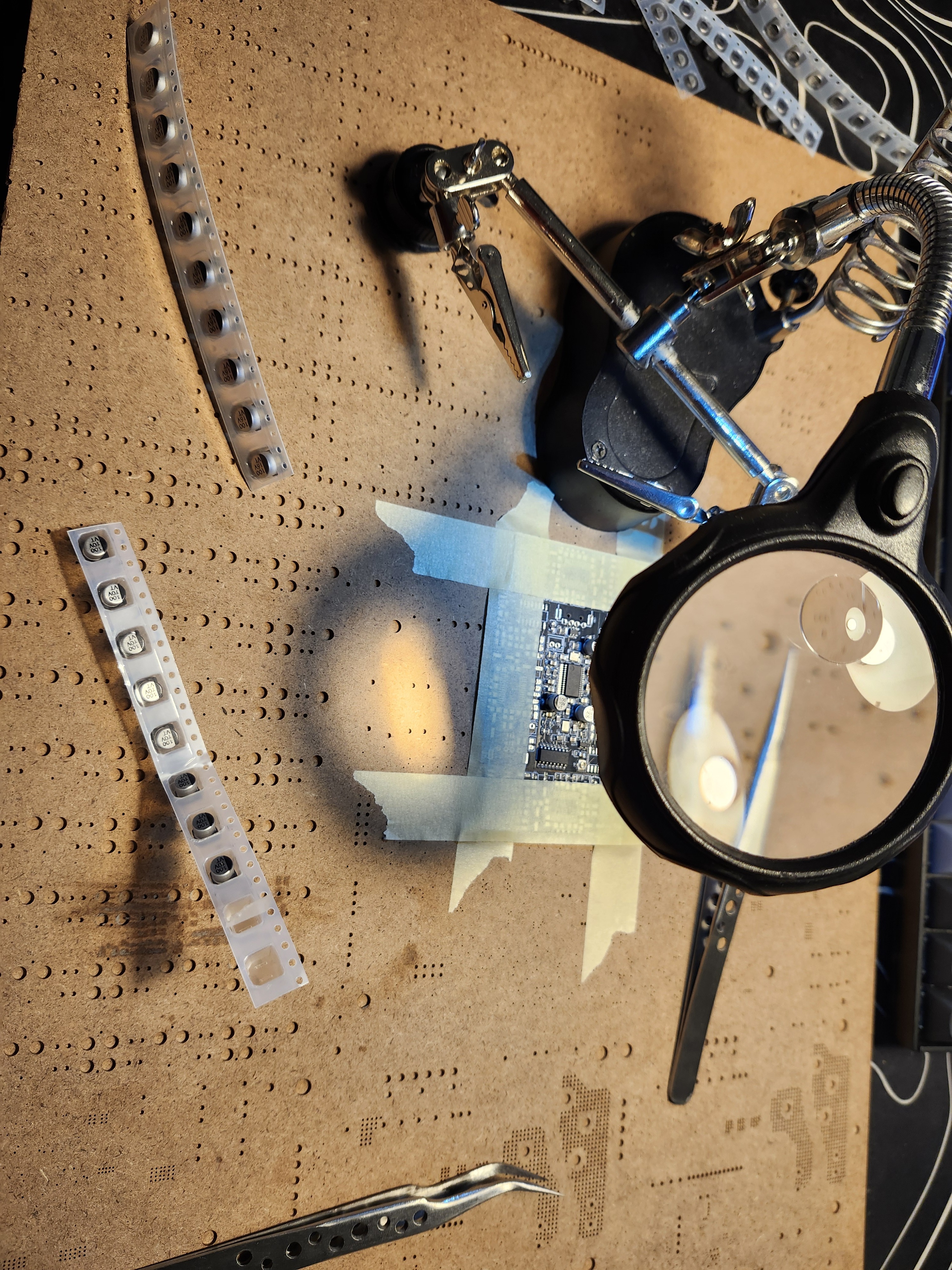
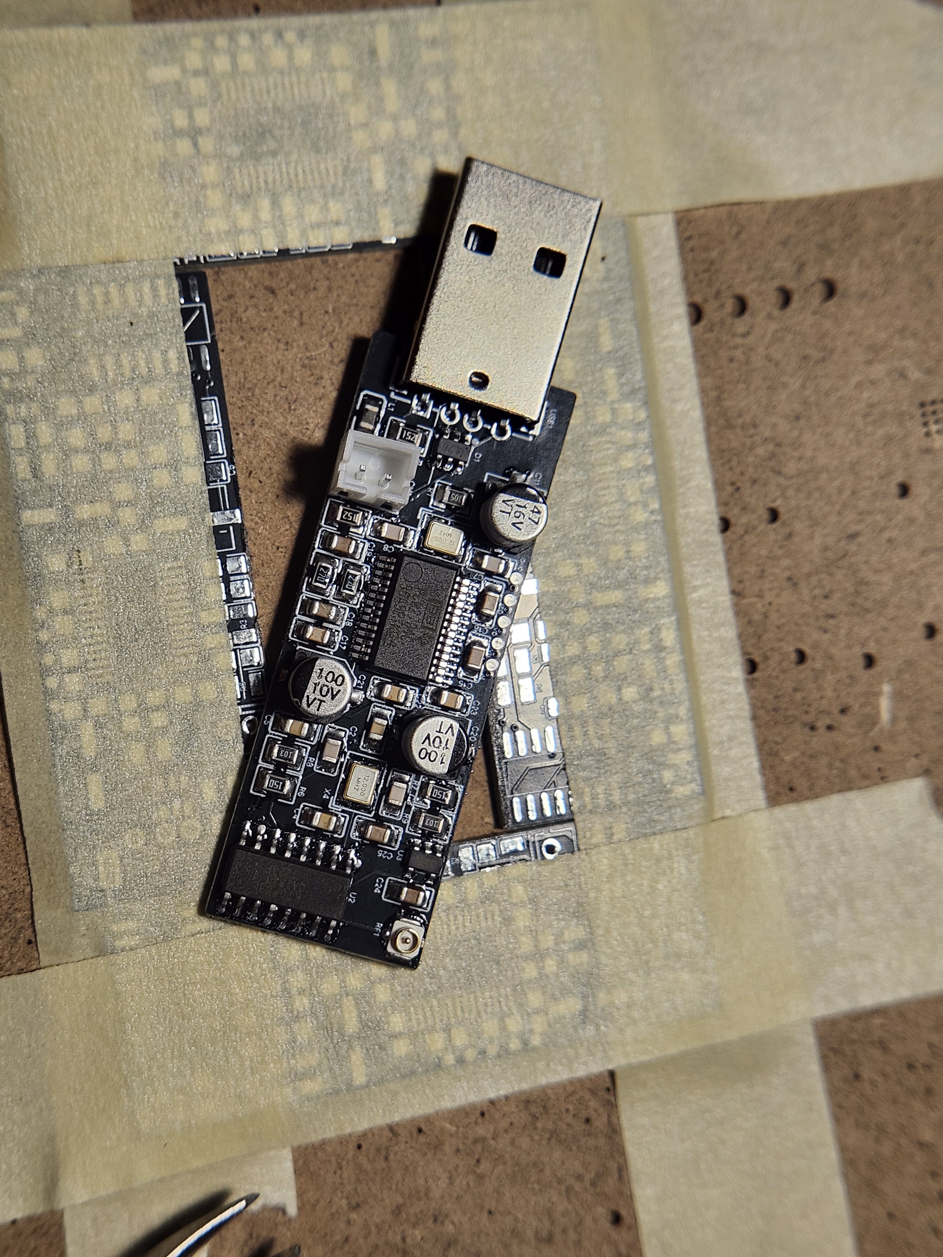
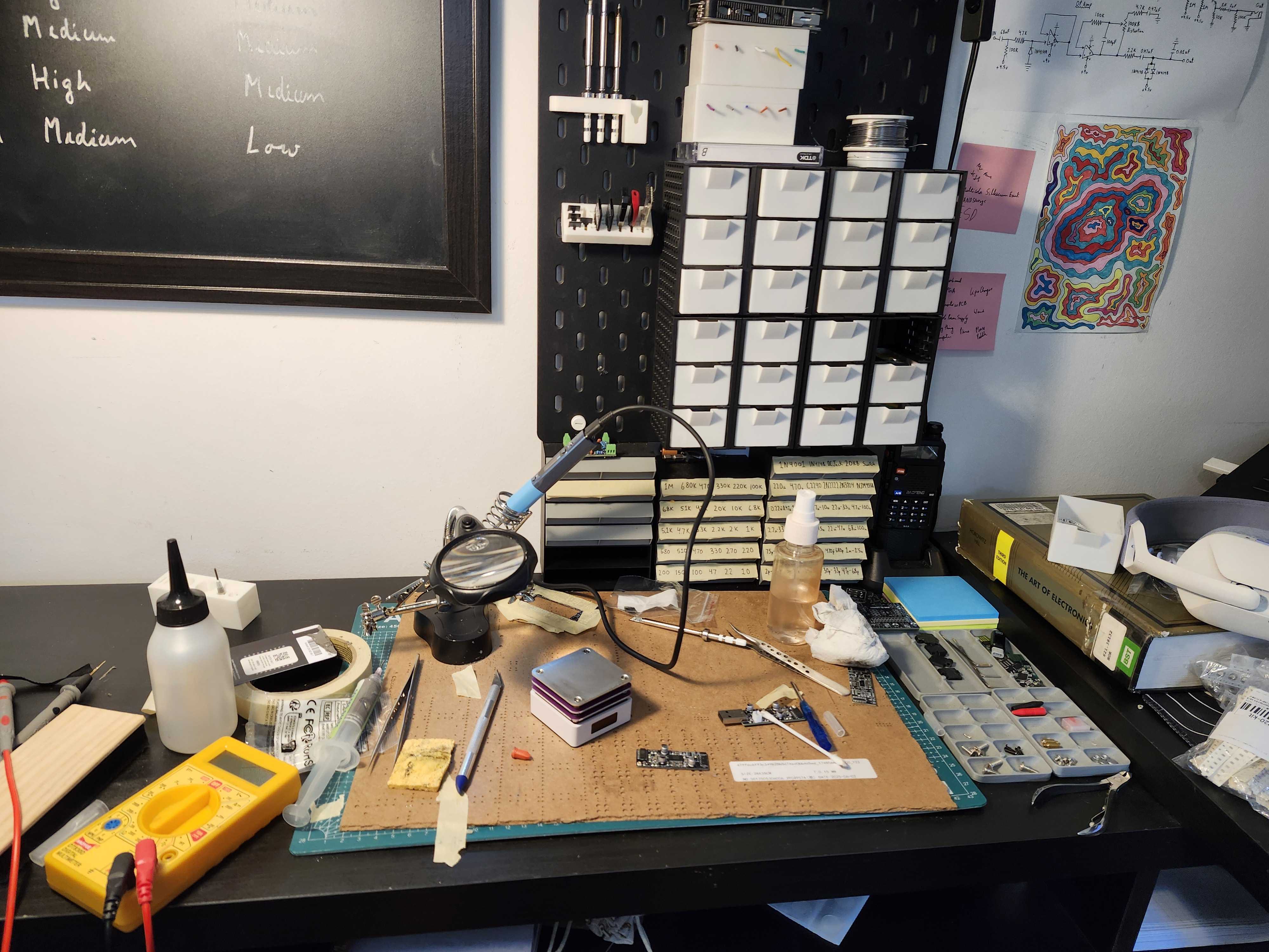
The Workspace
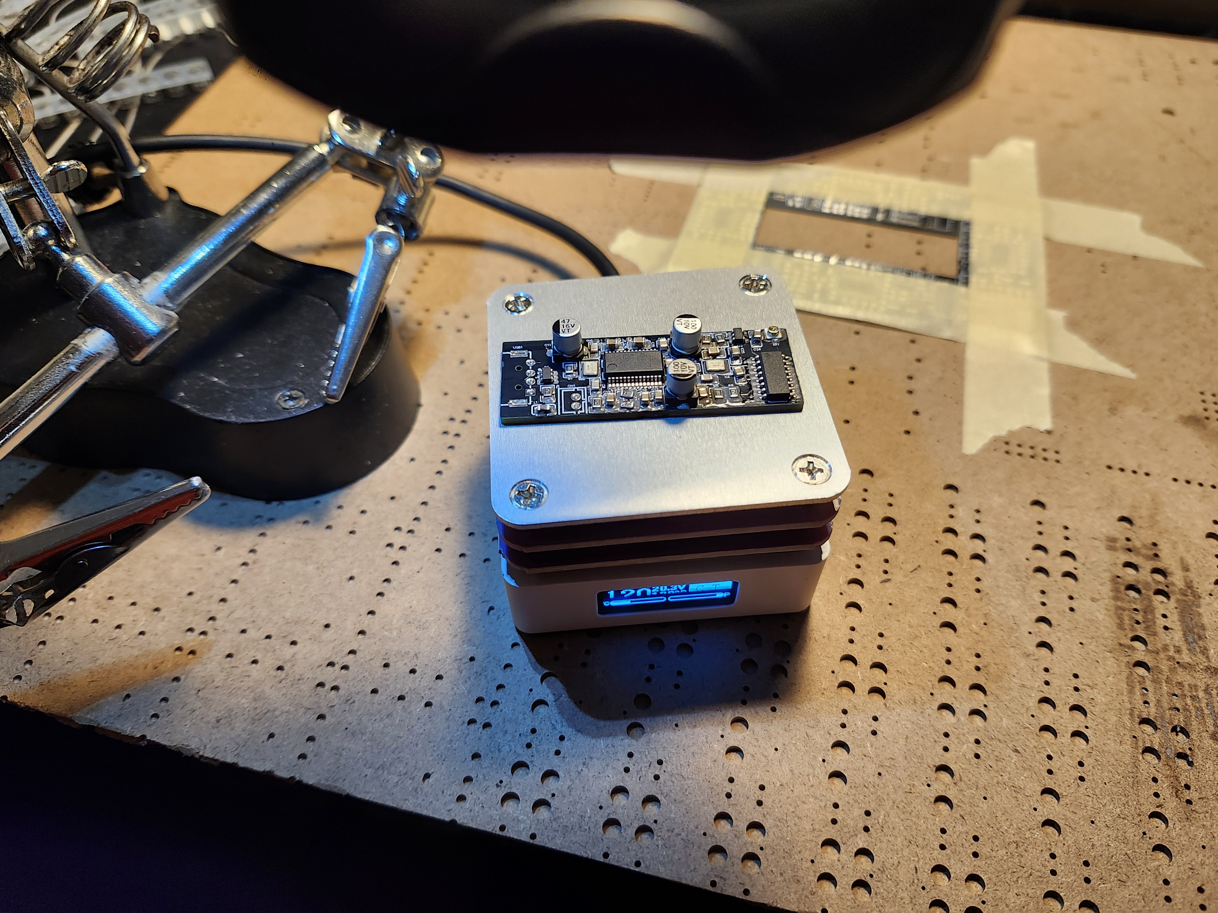
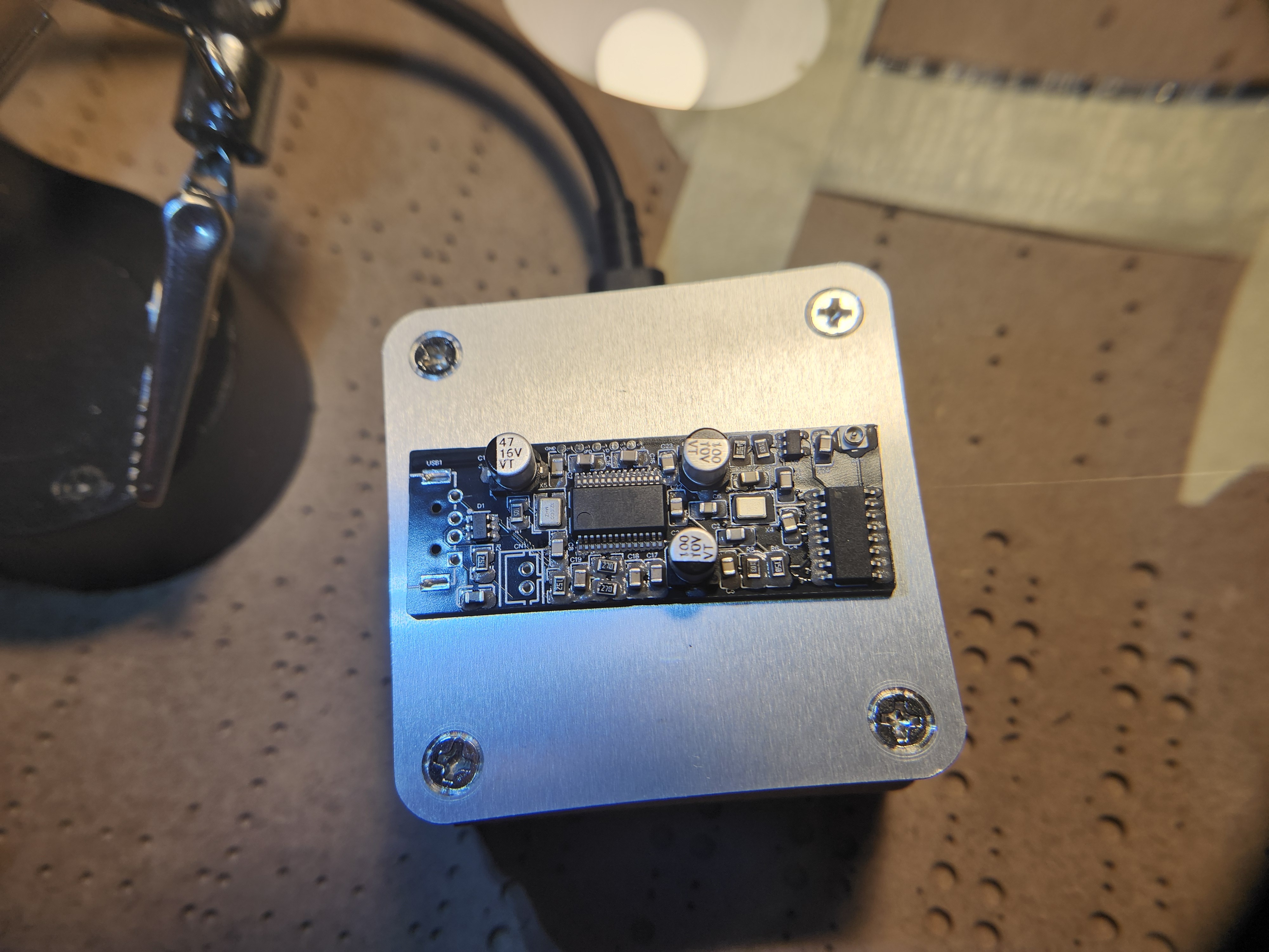
Assembled Board
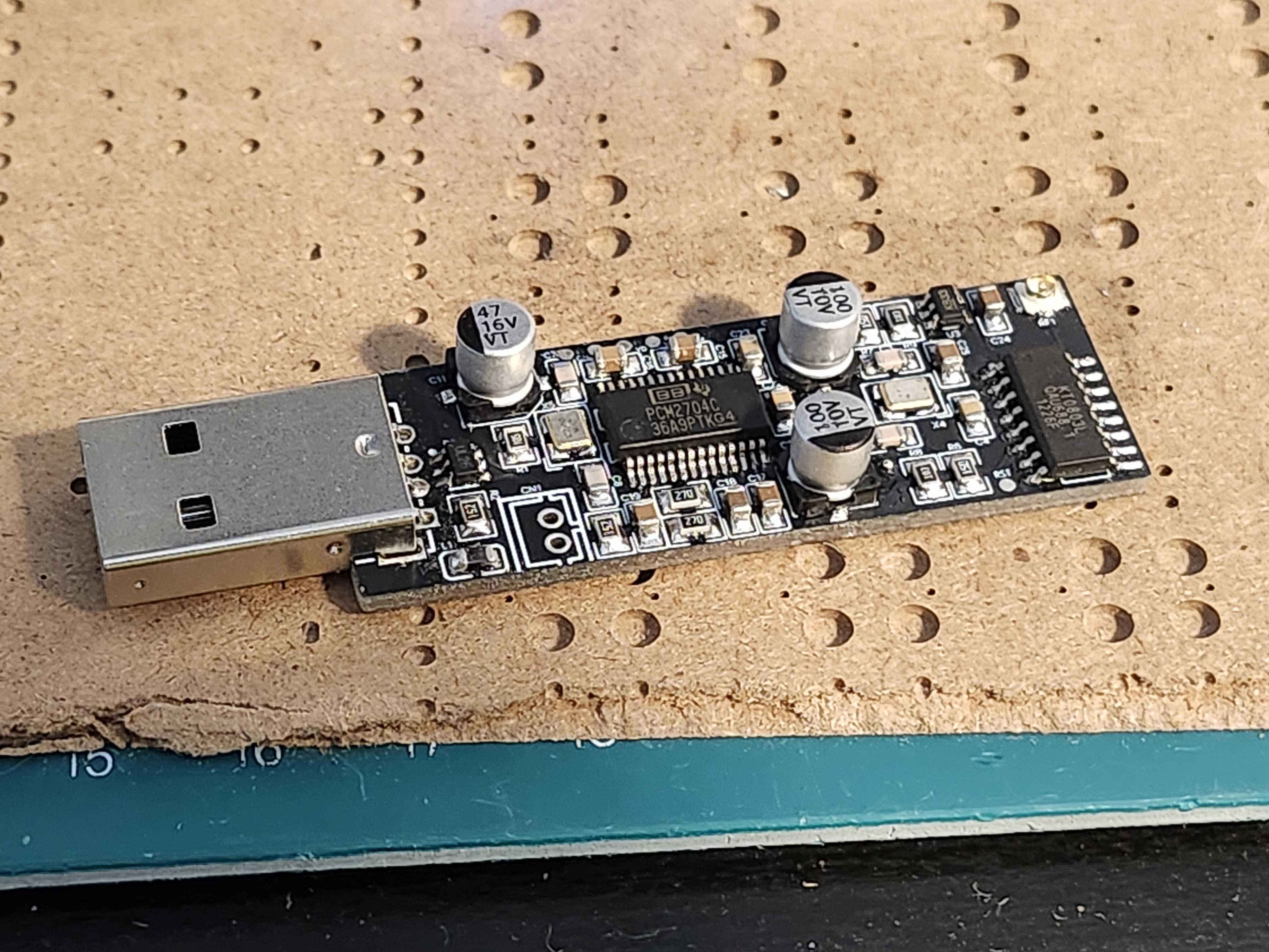
I spent about 30 minutes with my multimeter checking if anything was shorted, thankfully it was all good. I plugged it into my computer and neither my computer or the chip blew up, which was a really good thing. Windows detected a USB device but it could not get a device descriptor which was a problem. I spent about an hour at least trying to figure out what it was, scouring through Ti forums and the web. All sources said that its mostly likely an oscillator problem and it was! apparently the oscillator was not working at all when I checked it using my oscilloscope, I was kinda lost, I though maybe it was a load capacitance issue, but that wouldn't make the oscillator just straight up not work. After a lot of troubleshooting I found out I had actually placed the crystal in the wrong orientation, the crystal and its footprint were a bit different which caused this issue, I rotated the crystal 90 degrees and then it finally worked!
The board was being detected as a DAC by my computer and was showing up as an audio output. I played music on my computer and then used my Baofeng UV-5 to listen to it on 86Mhz and it worked!! Sound quality was really decent, almost sounds like what you'd hear on the radio, sounded a bit dry but maybe that's because of my Baofeng's speaker.
I played around with it a bit and then decided to set a different frequency by writing to its register. I wired up the board to my raspberry pi pico, shared the ground and 5v and then wrote a code that changed its frequency to 106.5Mhz, the code successfully wrote the new values to the designated registers but there was a tiny problem, these values were not saved on power off, so you essentially had to write to the chip every time it starts, I could unfortunately not test out the board on 106.5Mhz today but I will try again tomorrow.
Time Spent: 8 Hours
June 28th - I2C working
I finally got I2C working on the board, it turns out it already has inbuilt pull ups and I did not need add them externally on the breadboard. I connected the sda and scl pins to the pico and vibecoded a program that lets you enter a FM frequency and it then writes to the appropriate registers to set it to that frequency. The 2.4ghz antenna was pretty decent but was not strong enough to override existing FM broadcast signals, I touched the tip of the antenna on my breadboard power rails and viola! the breadboard is now an antenna and its strong enough to override FM broadcast signals in at least 5m radius.
Time Spent: 3 Hours
July 20th - V2
I started working on a new version of the FM Transmitter, this time I wanted to have a MCU on board so that I can directly talk over serial to the MCU and it would then forward that and talk over I2C with the transmitter chip. I spent most of my mine today just researching what chips to use for the MCU, I needed something small and something that didn't require a lot of passives. After some research I found the CH552 but it was kind of problematic as it had a weird toolchain and the datasheet was in all chinese, so instead I opted to go for the EFM8UBIOF8G from silicon labs, its a small OFN20 board and only requires like 4 decoupling capacitors to work.
Time Spent: 2 Hours
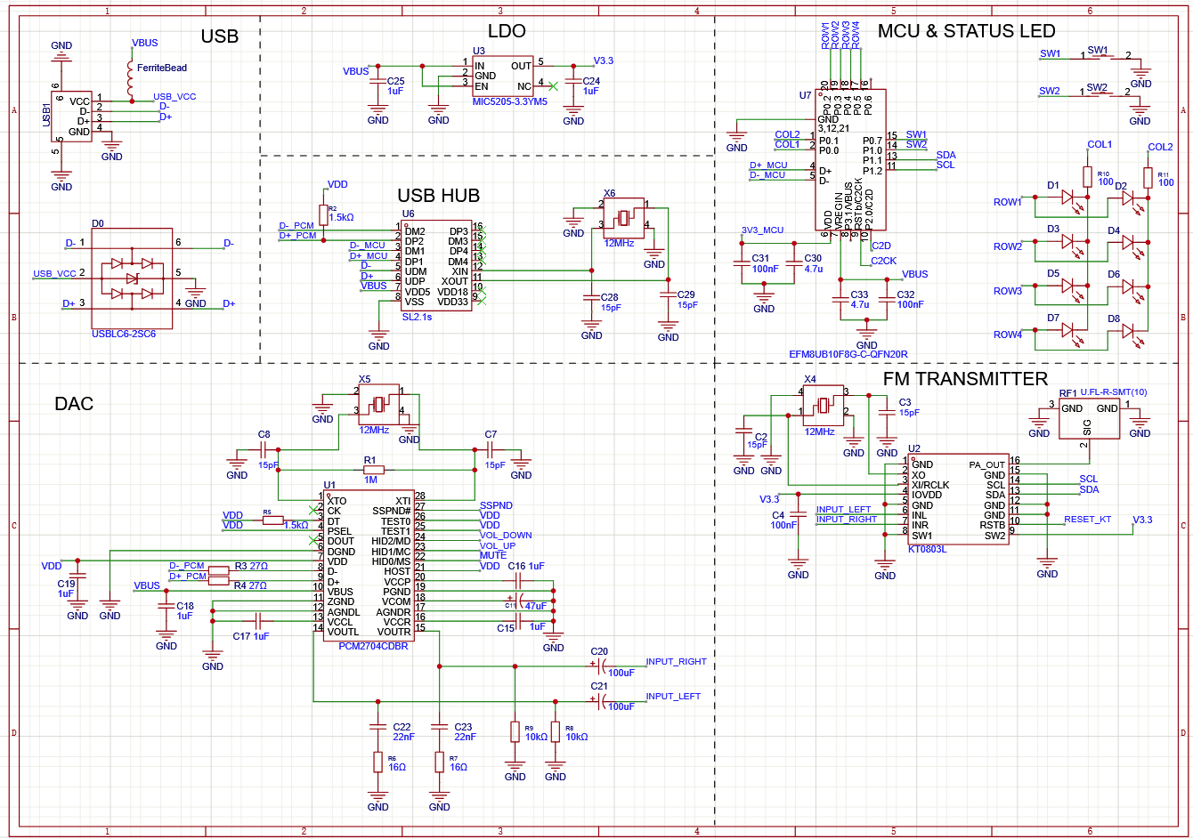
July 21 - Finished V2 Schematics
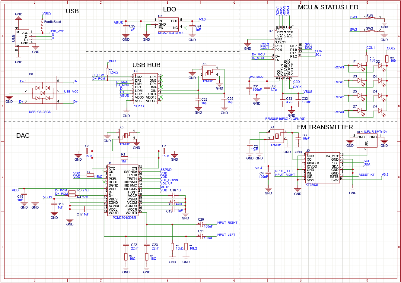
I finished up my schematics today, added a USB hub and configured it to have two downstream ports — one for the USB DAC and another for my MCU. I also wanted to have some status leds and a button to control the frequency on board. Since its the full FM Band (86.0-108.0Mhz) that's around 220 values (assuming .1f), displaying 220 different values in base 10 is well uhh... hard to do on a board using leds. Instead of base 10 I decided to go with base 2 or binary, this way I only need 8 leds to display 256 different values. I ran into another problem though, my MCU did not have 8 free pins, but the fix was pretty easy for this, I just wired the leds in a 2x4 matrix that way I only need to use 6 GPIOs and only 2 resistors (instead of 8). This will probably complicate the firmware a bit but that's a problem for another day.
Schematics
Time Spent: 4 Hours
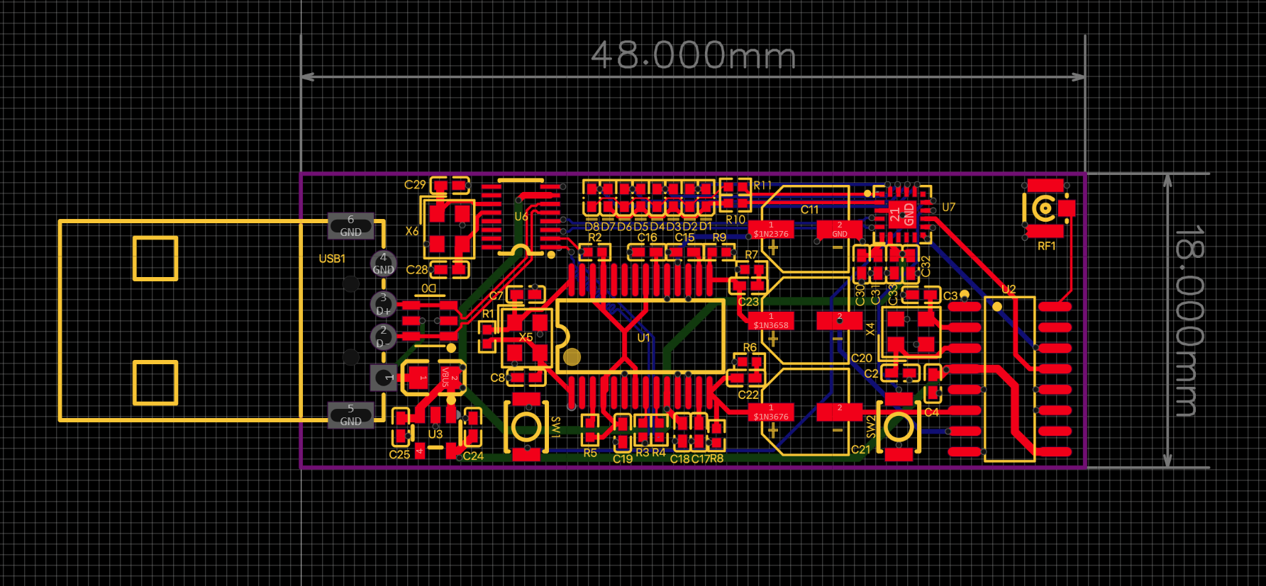
July 22nd - Finished V2 PCB
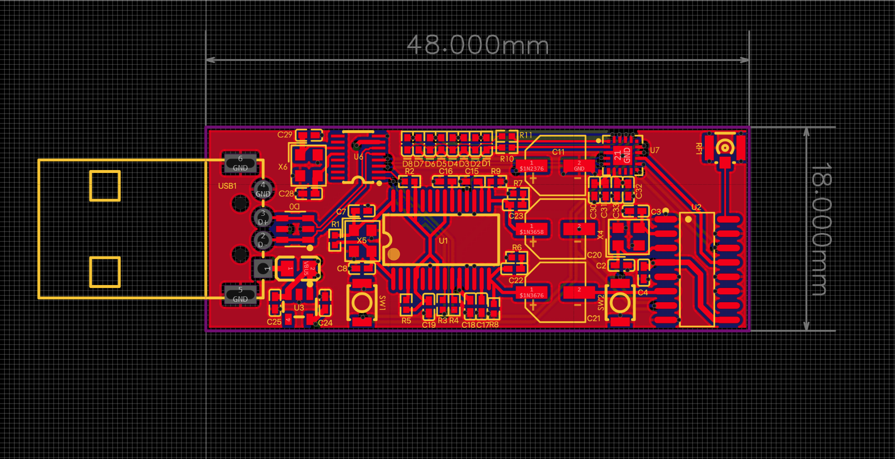
Finished laying out and routing the new PCB, I went with 0402s this time and oh my god, they saved up so much space, I had so much free real estate on my board now, I added my USB hub and my MCU and I still had free space, I reduced my board length from 50mm to 48mm, I could compress it even further but I was like why bother. I also went with a 4 layer design because I'm going to assemble it myself and the cost difference is like $2. The 4 layer stackup went like this -
Top - components+signal+ground pour Inner 1 - Solid ground plane Inner 2 - Chonky power traces + ground pour Bottom - Signal + ground pour
I don't know if too much ground pour is ever a problem but I guess we'll find out when I try to assemble it.
Updated PCB
Time Spent: 3 Hours
July 23rd - Fixing Errors
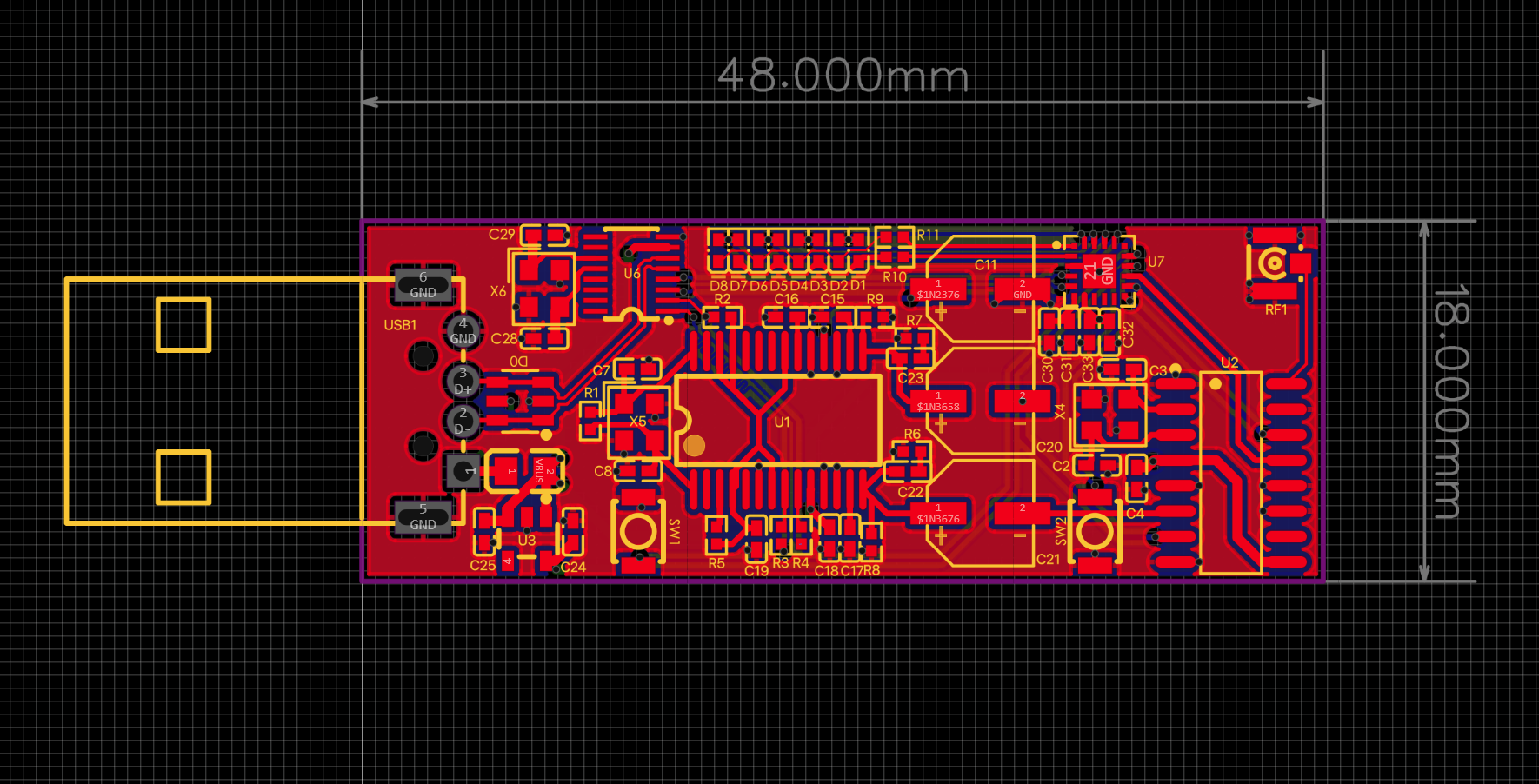
I posted this board on r/printedcircuitboard and someone mentioned that I wired up my ESD protection diode the wrong way, my vbus was actually shorting to ground. I fixed that up real quick and rewired it properly, I also just rotate my antenna ufl seat 90 deg clockwise so its just at a better position.
Updated Schematics
 Updated PCB
I also worked on creating the BOM for this project, and finding appropriate parts on lcsc for it. I made sure to pick correct parts this time (I picked up a crystal with a weird pinout last time and it threw me off).
Time Spent: 2 Hours
July 24th - Finishing Up
Worked on assigning components on lcsc for this project, I could find almost everything except for the Silicon Labs MCU, I unfortunately had to use Digikey for that. Also worked up on updating the github repo with all the update designs, screenshots , readme and more.