
Curtainopener
Curtain Opener
What am I making?
My plan is to make a compact device that is able to open and close my curtain with the use of a NEMA motor, it will also be powered by on-device Li-Po cells and be charged with a solar panel making it fully self sufficient with no need for any external power cables.
Time Spent Overall: 20 Hours
June 19 - Speedrunning the project
I have my advance functions final exam tomorrow and I'll be going to spurhacks right after it so I had to speed run my entire project.
Here are some notes I made on how this project was going to work-


The entire plan here is to have a NEMA motor connected to one end of the curtain and an idler the opposite end, and then by having a belt or a Kevlar string I can push and pull the curtain. all of this would be powered by 2 1200mAh lipo cells which will get charged by a 12v solar panel that's mounted on my window. Additionally everything here would be controlled by a ESP32 allowing me to setup routines or control it remotely.
I also spent at least an hour finding which parts to use and found decent modules for almost everything in my project
Time Spent: 3 Hours
June 26th - CAD
I basically finished the entire CAD required for this project and here it is-


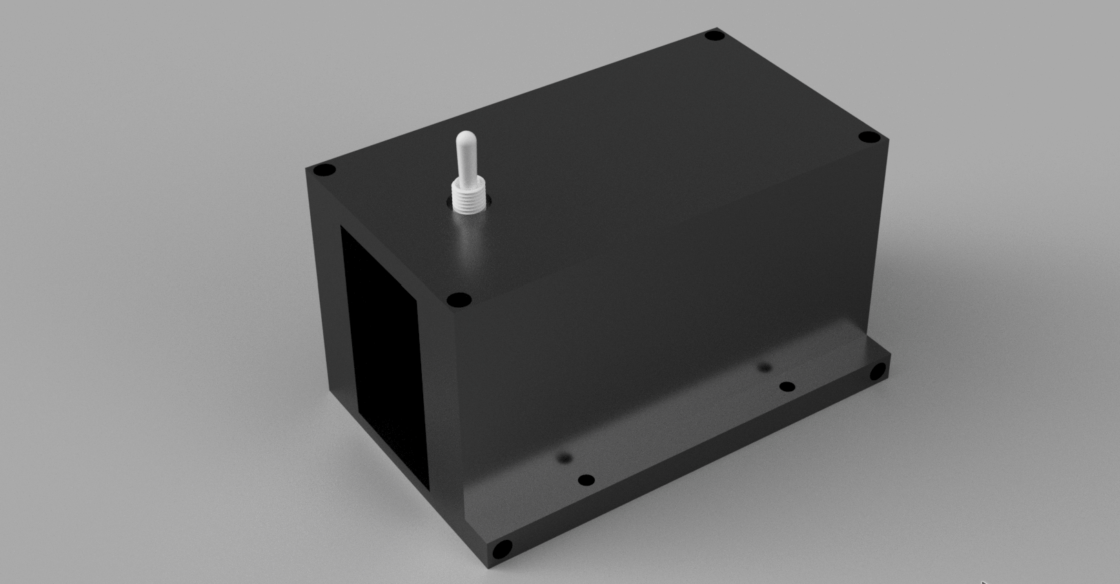
This is essentially a very compact (almost 8x8x8cm) box which houses all the electronics, and the batteries. I've opted to go with a perfboard for this project instead of a PCB mainly because I wanted to use upgradable modules, having a perfboard allows me to update and upgrade things in the future whereas a PCB really keeps me locked in to what I have.
The box has plenty of space inside to house all my required electronics, it also has a separate sort of isolated section for the Li-Po cells, I've added grills to the sides to allow for ventilation and heat dissipation from the batteries as I don't want them blowing up or catching fire. I'm using 2 1200mAh 18650 cells wired in parallel to output a total of 3.7v with 2400mAh capacity. the 3.7v output would be boosted to 12v for operating the motors and that 12v would be stepped down to 5v to power up the ESP32.
Also spent some time today working out the BOM for the project and here's what I ended up with
 I still need to add up a few more things but this is more or less the core components required.
Time Spent: 5 hours
28 June - Finishing Up
Made a official wiring diagram for the project

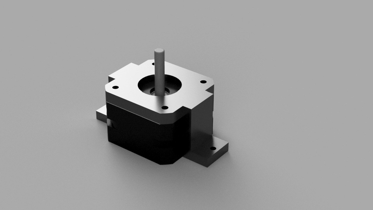
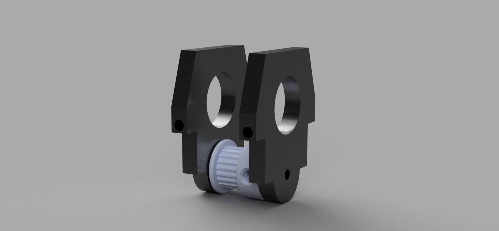
Also finished up the CAD for the project. Made a v groove pulley for the motor and another v groove idler that uses a 608 bearing.


Also designed a mount that screws into the main box and also screws into the wall

Also updated my BOM a bit

Also spent some time updating and creating a github repo for this project
Time Spent: 4 Hours
15-22 July
Updated the design a lot!
got rid of the solar panel and batteries to reduce cost, just went with a wall adapter for power.
new motor mount
new idler
new box
Time Spent: 6 Hours
23-24 July
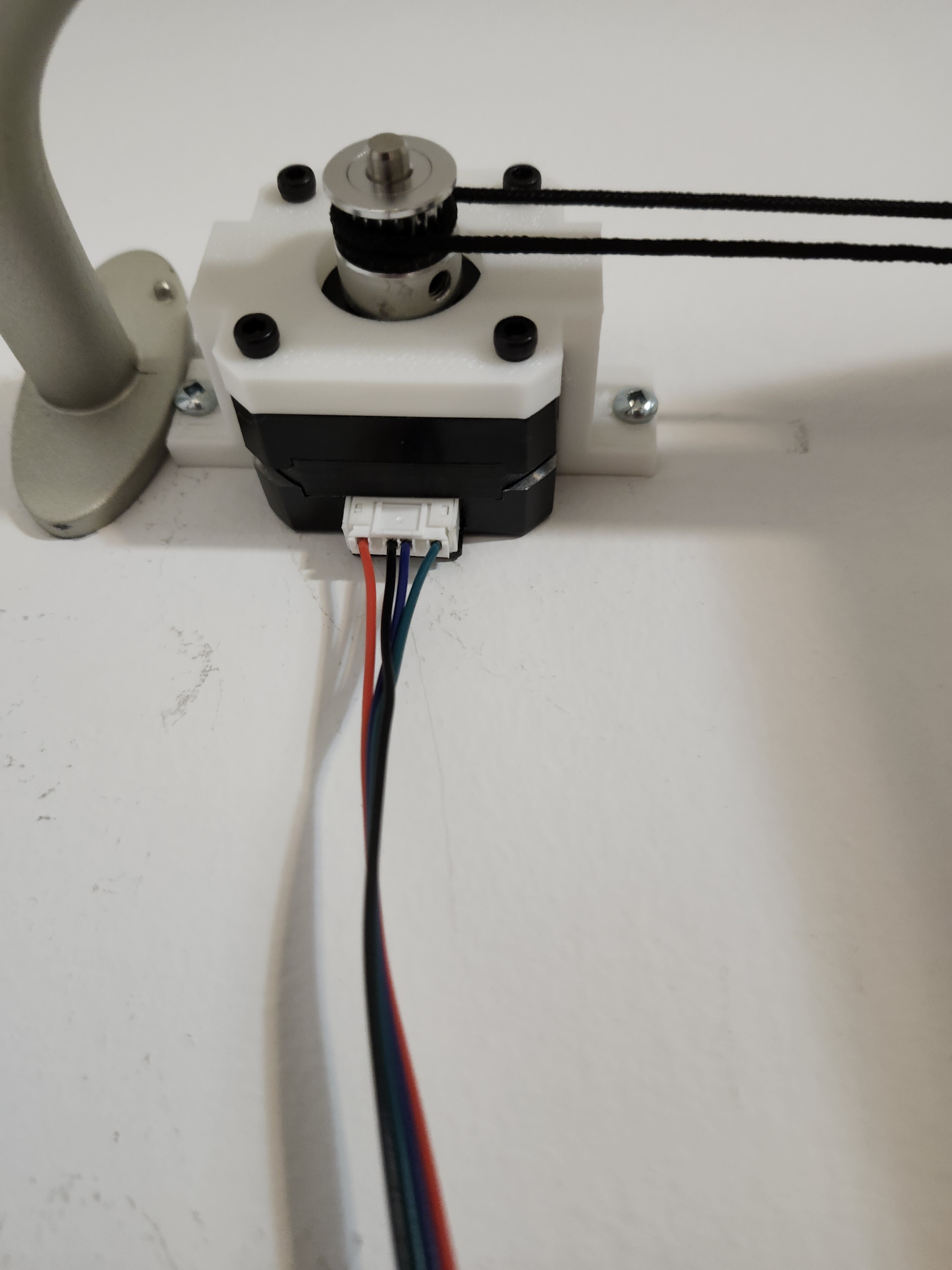
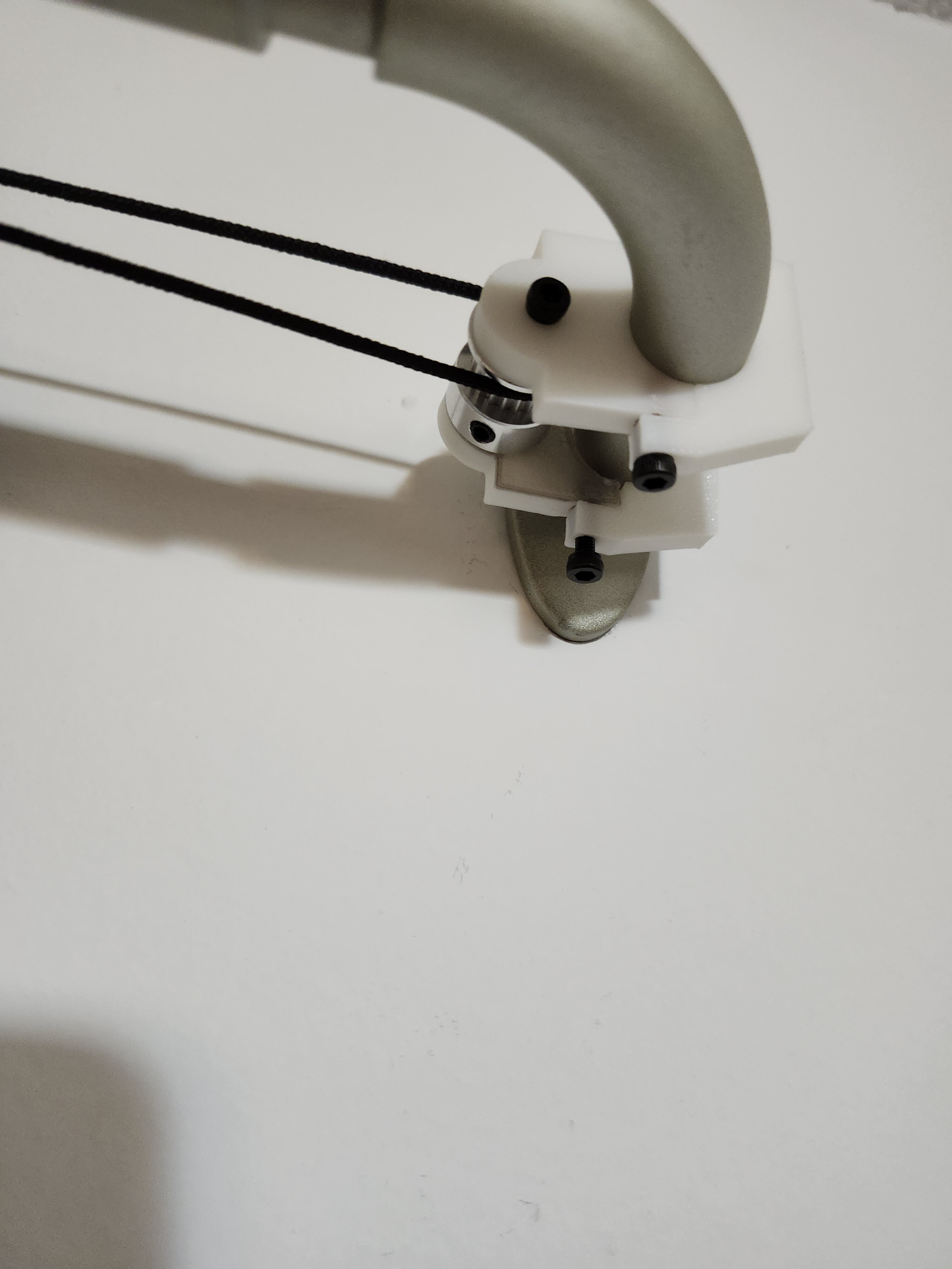
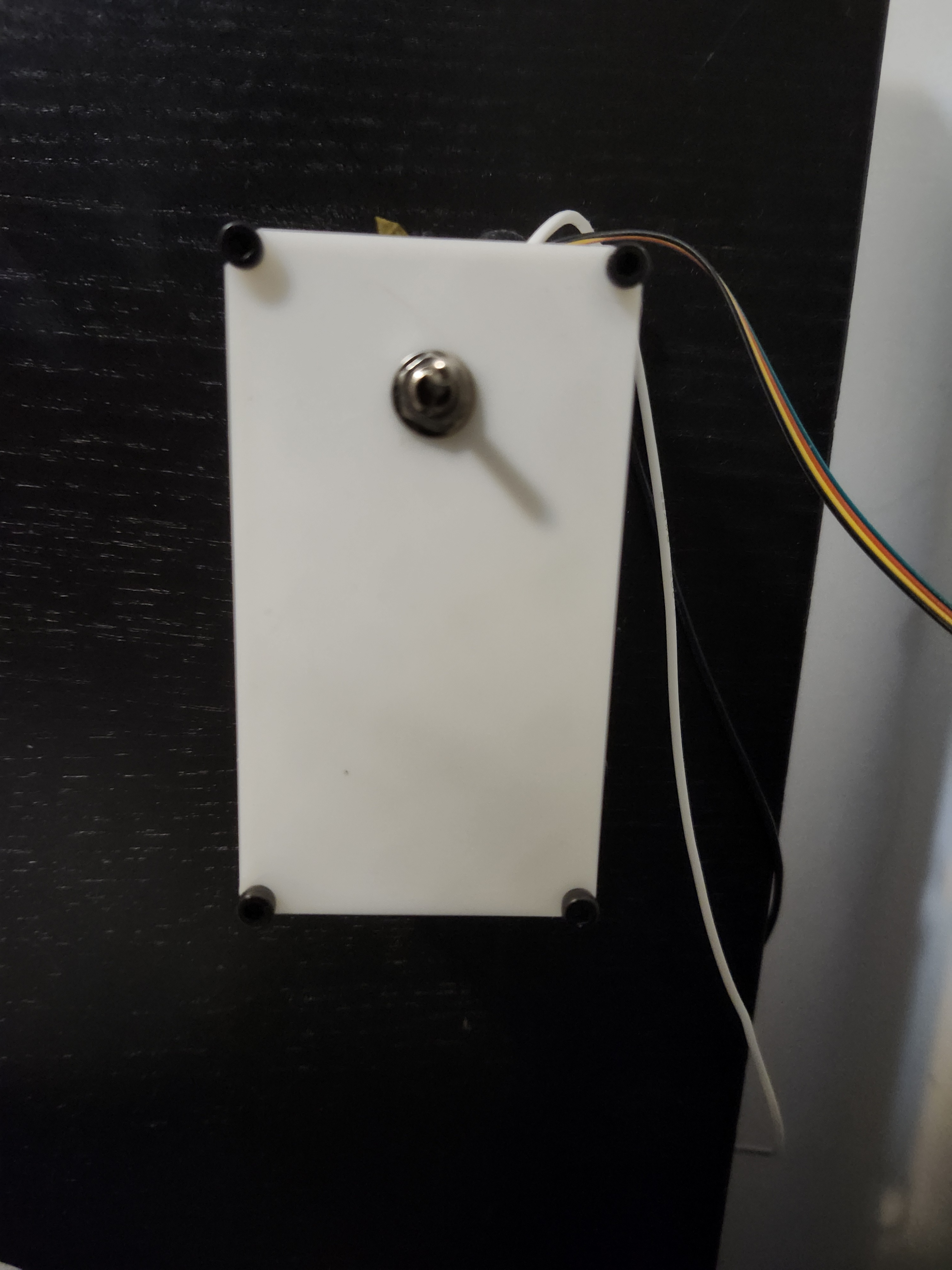
I printed out all the parts and mounted them on the wall, vibecoded a little web interface to control it! These are the real life pictures of the finished project-
Motor
Idler
Enclosure
And this was the vibecoded firmware I made for it. It basically just opens a web interface where i can control the motor from
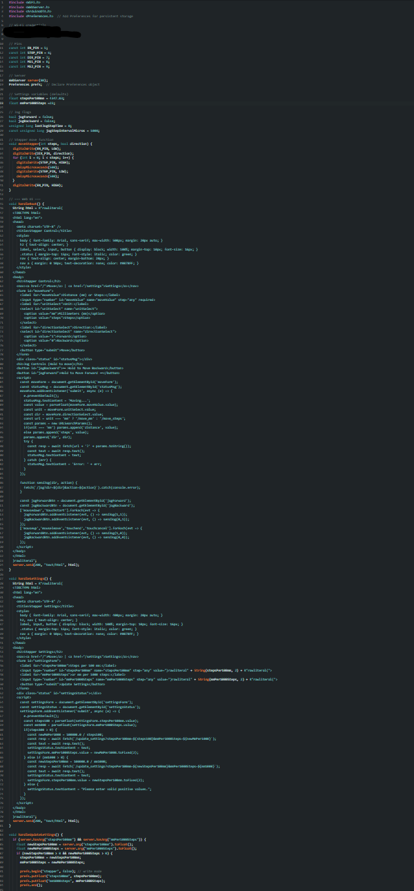
The demo should be in the project readme!