
Clock Controller
Hacking an analog wall clock to run off a Xiao ESP32-C3. Besides timekeeping, will be a timer and stopwatch. Controlled via BT or wall mounted keypad.
792025
30m Begin! I have a clock motor laying around (for an analog mounted wall clock). The ideas is hacking it to do whatever I want. Mode 1 is regular clock. Then, if you press start, it runs like a watch chronometer.
Found this article with a clock controller:
RasberryPiMag-AnalogClockController.pdf
It looks like they’re just running 10 mA pulses using a motor controller. I bet I could wire directly from a board that has better pins.
Motor driver specs: https://potentiallabs.com/cart/l293d-ic
Then the output is turned down with a 470 ohm resistor
7122025
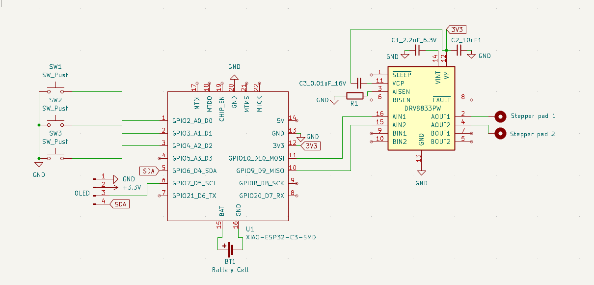
45m Sketch the schematic Motor controllers are weird. The wiring diagram I'm going off had several extra traces I don't need (they're for an extra switch he was using). Once I figured that out, I read some articles about H-bridges to figure out the motor controller and drew the traces.
The switches are a one-row matrix to save space.
30m Read the ESP32-C3 datasheet. The datasheet said the ESP32-C3 didn't have an internal clock, so I asked on the Slack. @luteron6 helped out - I was reading the schematic for the chip itself and not the module. Since the module has a clock, I can continue on.
7132025
1.5h Make the schematic.
Learned a couple helpful things. Headers are called Conn pins, and that's what I used for the OLED and clock input.
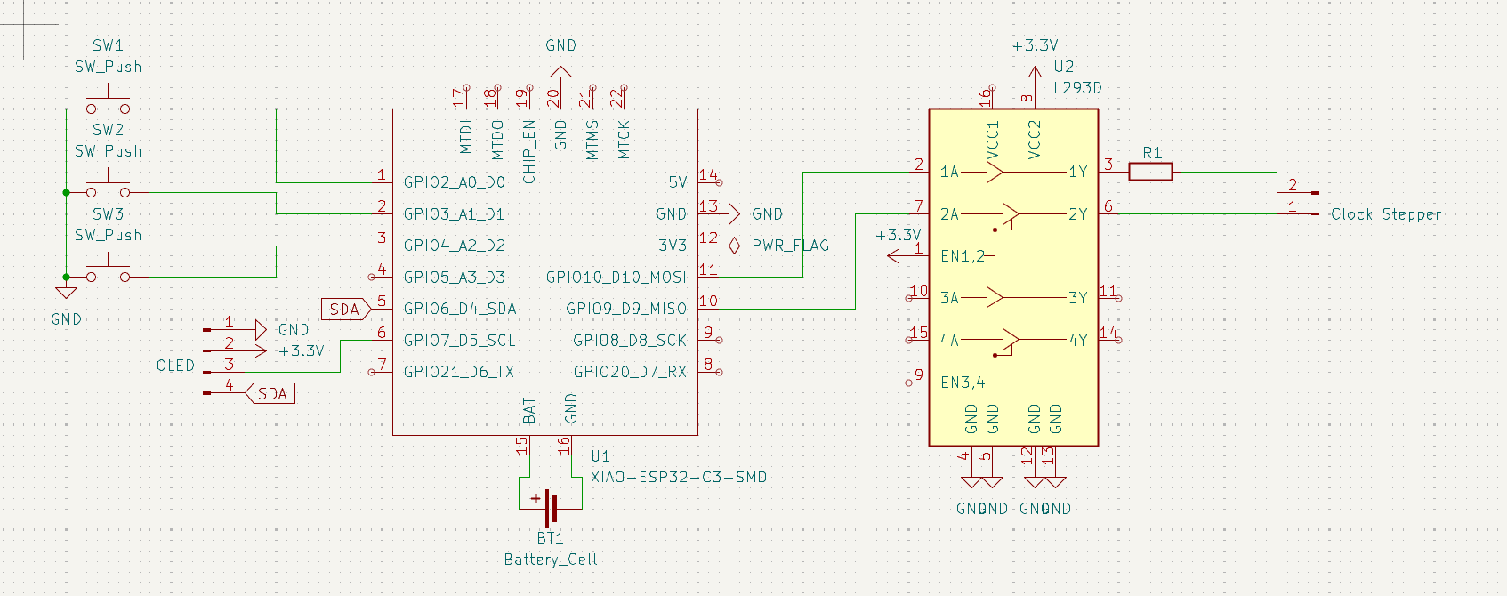
1h Motor controller swap I was putting off figuring out how to jump from the 3V3 to the 5V for the L293D. I could add some components to raise the voltage. But since the clock stepper is a Lavet-type stepper motor, it likely draws 1.5 volts, so raising, then lowering, the voltage isn't useful. Instead I'm going to use the ChatGPT recommended DRV8833 which operates down to 2.7V due to the MOSFET.
8/20/2025
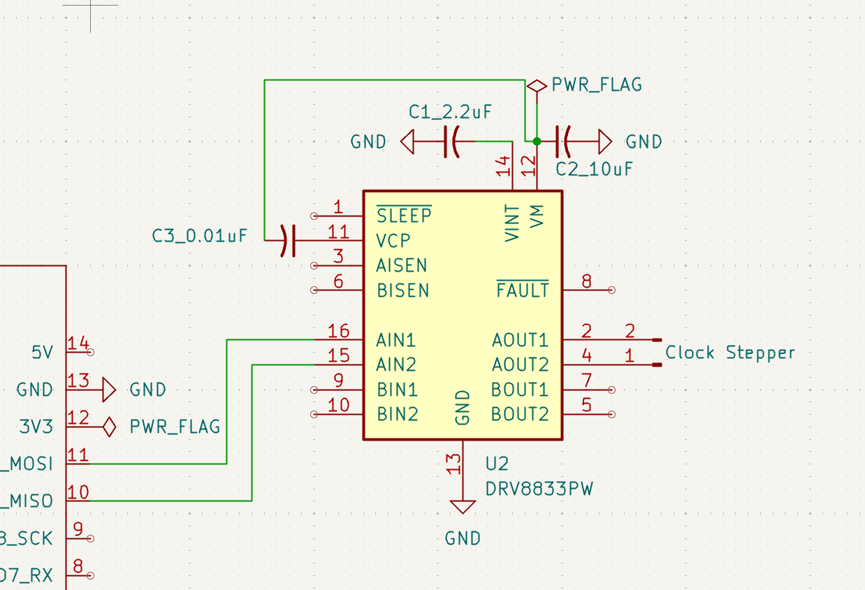
30m Moving to a DRV8833 motor controller bc it has negligible on-board voltage drop, so I can pipe in 3.7 and get out about 3.7, which is what I need for the Lavet-type stepper motor. Lavet steppers use 1.5 or 3 volts. This article is helpful: articles
60m learned how capacitors work to set up my motor controller. this Reddit post explained the bypass capacitors are just capacitors functioning as bypasses for AC noise on the circuit - caps store DC and pass AC, so it keeps the circuit at a useful operating voltage.
8/30/2025
2h I need ceramic capacitors bc they filter noise better than electrolytic The VCP is how the mosfet turns on, and the capacitor is there to boost voltage (vcp voltage has to be higher than VIM)
not really sure what the VINT is there for
VCP needs a bootstrap circuit that I don't know how to make (yet).
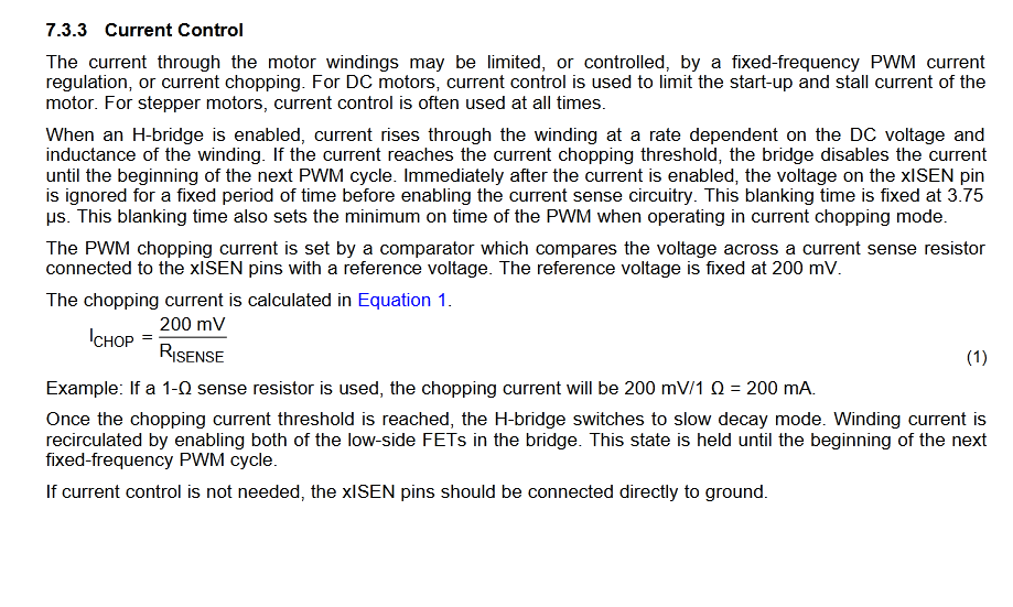
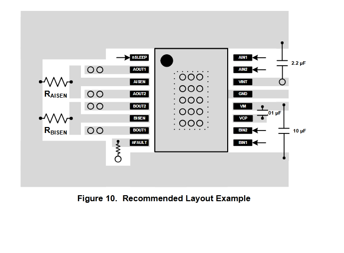
I might need a resistor at AISEN to limit current:
Thick trace from VM to ground
There's no resistor on the high-side pin?
8/31/2025
1h
ok so VCP is a flying capacitor - the charge pump circuit is inside the chip.
I added the resistor to AISEN, which is ground for the A circuit.
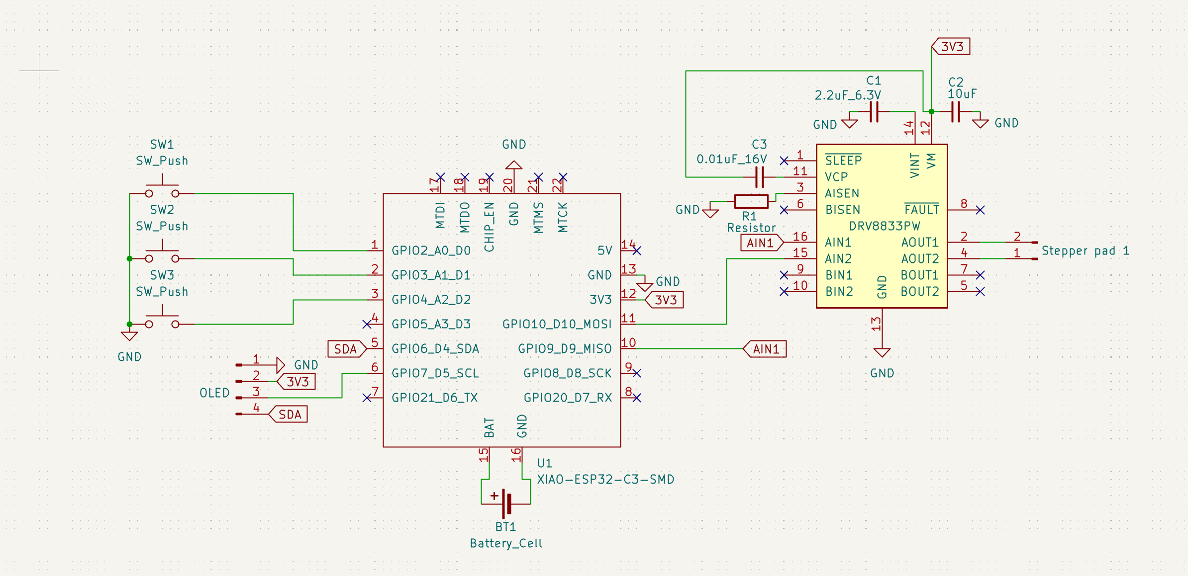
Pretty confident this schematic will work going forward:
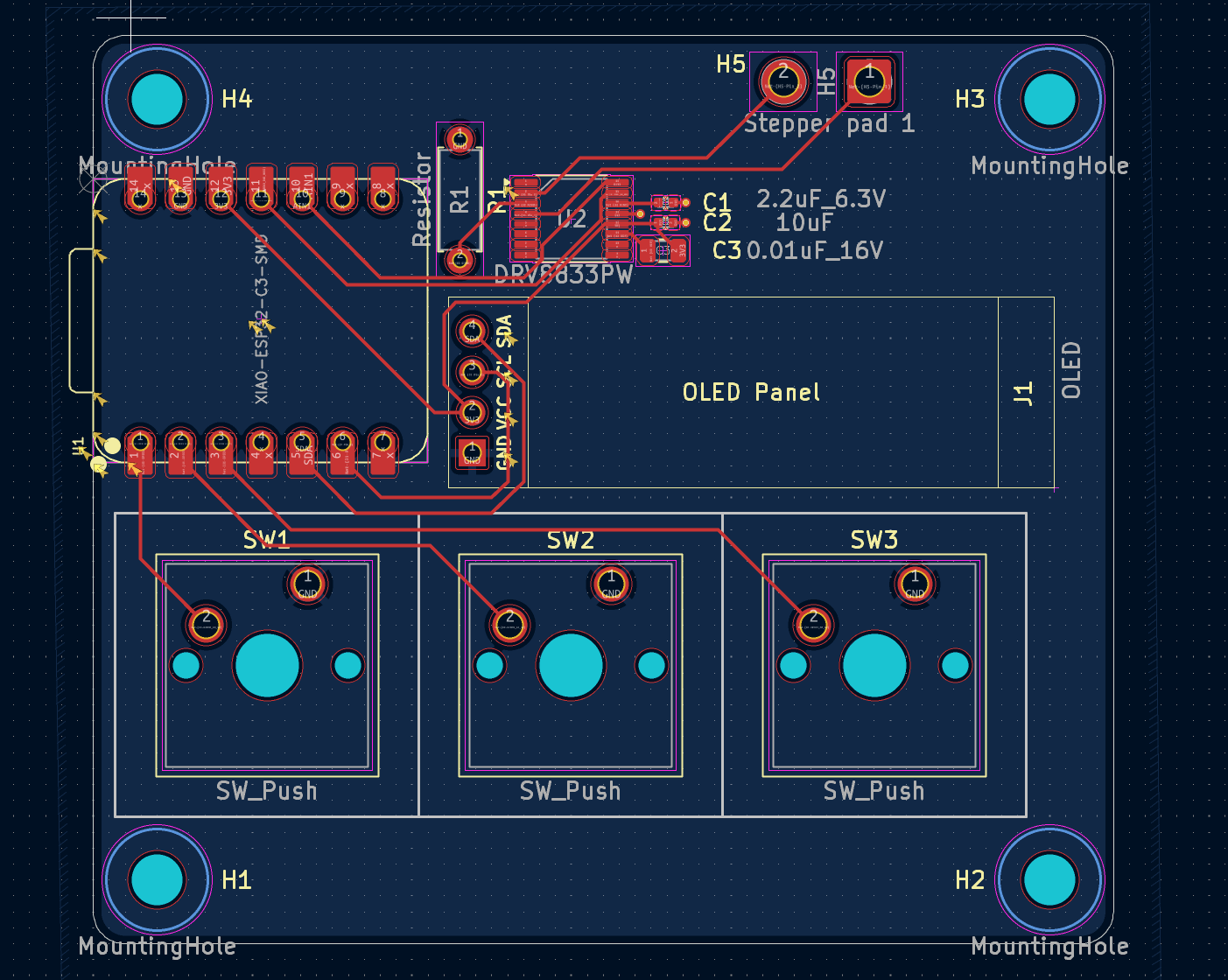
Goals: 1. make a pcb with roundy corners bc I like 2. find that article with all the good tips on schematics in the secret hackclub docs
9/9/2025
1h Sooo looks like I've been keeping two journals by accident. I moved all of the new journal to this journal. Anyway, today I figure out what footprints to use for the capacitors (they come in just a few standards). I also learned that for schematics you need a reference designator (R1) and a value field (5 ohms). So I fixed that on the cad.
My capacitors are attached to the ground plane with a few vias, because they're surface mounted on the opposite side.
This is the current PCB design:
And this is my schematic:
I got trained at the innovation lab so I can use their soldering irons now.
9/28/2025
Learned from finishing the keeb that unless I have a lot of components, having JLCPCB assemble isn't economic.
2h generated it as assembled, assembly cost ($15) was basically the cost of components with the JLCPCB coupon ($9)
Sometime in December
2h Built a hacky case mount to try and get some steam
12/31/2025
1h Finally attacked the BOM and found all the stuff I need on Digikey
1/5/2025
30m Sanity checking my BOM. Digikey parts cost $15.15 + $6.99 FedEx Ground coming to $22.14
To get the same items from Ali Express | Item | Cost | Link | | ---- | ---- | ---- | | Xiao Esp32-C6 | 14.37 | www.aliexpress.us/item/3256809265960807 | | 3.7v Li battery 500mAh | 11.58 | aliexpress.us/item/3256809202812025 | | 2.4Ghz Antenna | 2.46 | aliexpress.us/item/3256806242646249 |
These numbers aren't the best (I could probably get the battery cheaper and the Xiao ESP32-C6 is more expensive when not on sale), but I'm satisfied Digikey is the cheapest option.
_ Write the firmware Arduino is the best supported IDE, so I used that to write the firmware.
Minimum Viable Product: * A default clock state where the Xiao makes the stepper run like a normal clock * A timer function where the Xiao sets the clock to count down till noon * Key controls: Zero/Show-current-time, manual-rotate-forward, timer start/pause * OLED display shows time or timer, depending on what the clock is doing * Control mapped to a HomeAssistant dashboard
Other useful features: * running the Lavett at speed could throw the hands out of wack. Reflective sensors are a cheap way to verify everything is zeroed correctly * Or do I want a servo motor controlling the gearbox instead? * stopwatch features
25m pulled apart the clock mechanism to find the stepper and gears. When I plugged in the battery the drive gear spun insanely fast. If it's moving that fast and then being geared down, speeding it up with a higher voltage will at least slip a gear or worse blow the mechanism. I need to find a better way of driving this thing - looks like I'm buying a stepper