
Total time spent: 38 hours (yes I'm slow)
2025-07-04 - Where to begin (5 hours)
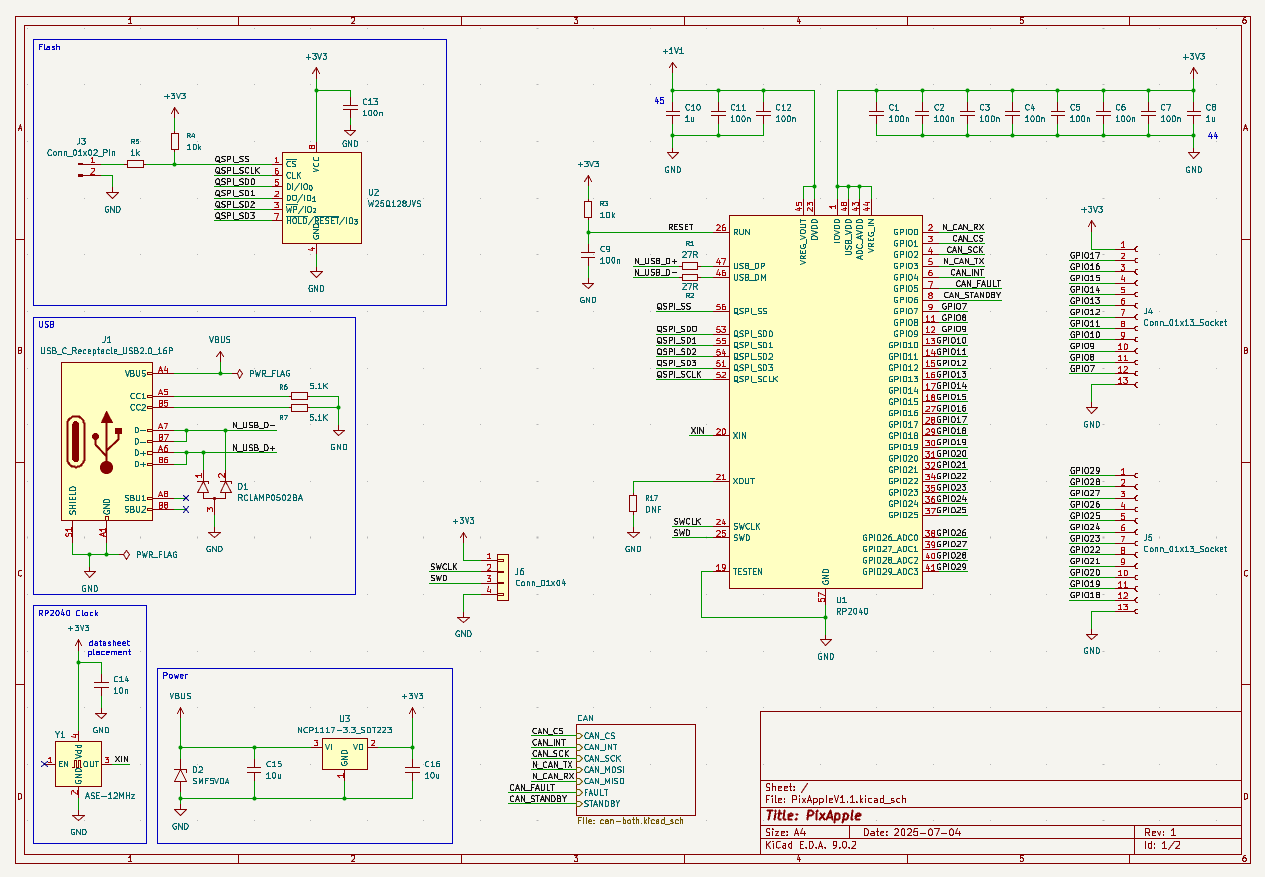
This is a starter project so I can learn how to actually design a keyborad with the RP2040. So far I've decided on Bluetooth support + battery charging. I'm tempted to make it waterproof, whatever that means for a development board, so I can stick it in a submarine sometime in the future. Who knows. Maybe. So far I've done the relatively basic task of setting it up with the power capacitors, pull up resistors and the likes. Only gripe I have right now is reading documentation is a chore.

2025-07-05 - CAN we do it? no (3 hours)
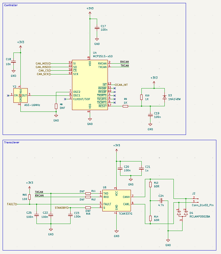
I want CAN. It'll make routing logic/commands/data to and from various parts a lot easier. Only problem is I have no idea what controllers to use. A preliminary search shows that the MCP2515 the CAN controller is a good fit but the transmitter the MCP2551 isn't. MCP2515 can handle +3V3 while MCP2551 needs +5V. So we're ditching MCP2551 for SN65HVD230. Whoever named these needs to be uhhh.... questioned.
Work is slow. So many pages of documentation on documentation. Mainly getting the crystal oscillator and reset pin of all things working. And guess what! My hirearchical sheet was drawn in the wrong grid size because I somehow clicked N by accident. That screws up all the tags and you can't connect to them. Now I have to redraw the sheet. I hate KiCAD sometimes. Why on earth would it let you change grid size if it'll break everything in the schematic??? I'm sleeping now.


2025-07-06 - CAN re-schematic (5 hours)
Redo following (https://ww1.microchip.com/downloads/en/DeviceDoc/MCP2515-Stand-Alone-CAN-Controller-with-SPI-20001801J.pdf). Hopefully it went fine. The only thing that I'm slightly sketched out by is the series resistor R9 in the CAN clock. I'm not really sure how to calculate it and the ABM8-16MHz datasheet says nothing about it (https://abracon.com/Resonators/abm8.pdf). For now I'll just use the same resistor the RP2040 docs said to use with the ABM8-272 but hey at least I can desolder it if needed.

Use this to figure out what pins the IC can actually connect to (https://datasheets.raspberrypi.com/rp2040/rp2040-datasheet.pdf).
DRC finally has no complaints! I hate rewiring though. Time to add the CAN transmitter (https://www.ti.com/lit/ds/symlink/sn65hvd230.pdf?ts=1751731839553). Yippee JLCPCB has it as a part (how much does assembly cost... I'm scared this'll be super super expensive). We're doing split termination on the CAN bus because we can. Also because I dunno if my signal will be clear at all so I'd much rather have a working CAN bus than a dysfunctional one. I finished schematic-ing up the CAN controller, the MCP2515 and the transmitter, the SN65HVD230DR.

2025-07-07 - Breakout (8 hours)
https://youtu.be/ySuUZEjARPY Goated video.
Finished the schematic. Hopefully.

Added all footprints.

That was a total mess. I'll finish the rest of it tomorrow. Routing the CAN chip looks fun. The lines are all crossed and I'm scared that the vias will mess up the ground plane somehow.
2025-07-08 - Redo (6 hours)
Ok so uh I might be stupid and I might have placed all my components too close together. And uhhh... Well whoops they intersect physically so it's time for a complete redo. Yay. I'm having fun! (it is kinda fun though)


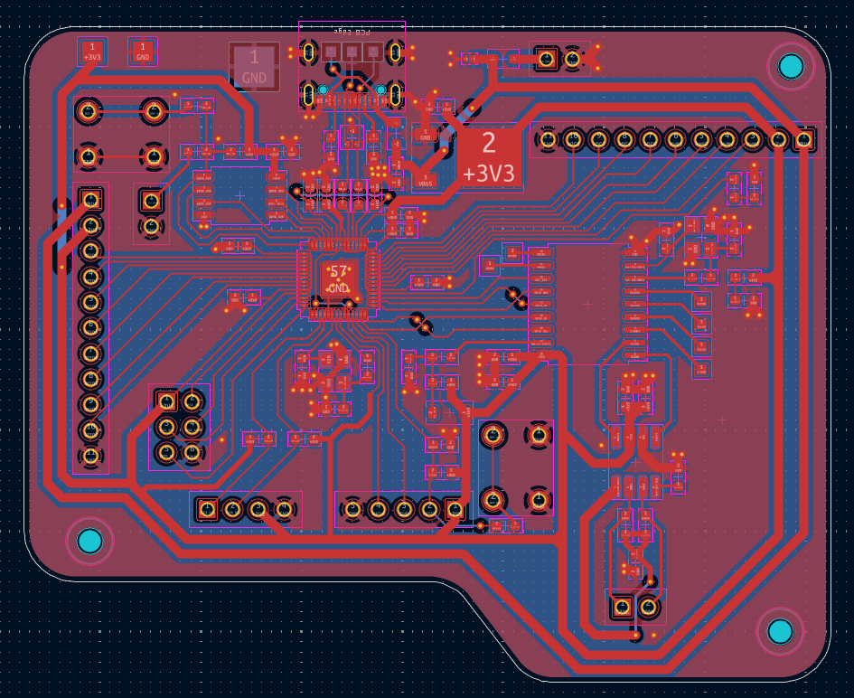
Routing this is a pain. I'm using 0603 SMT parts because I want to practice soldering SMTs however that means that I can't fit my desired number of capacitors on the board. There's simply too many of them at the top of the RP2040 there. Alas.

2025-07-09 - FINALLY (8 hours)
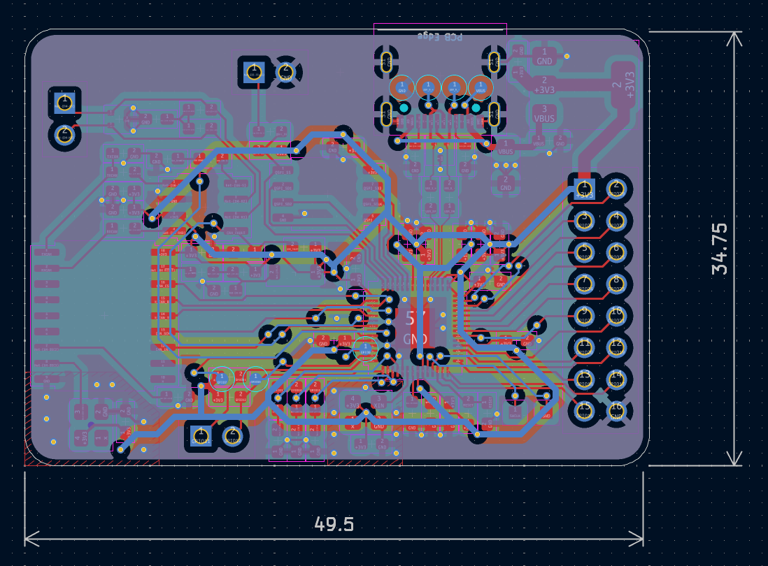
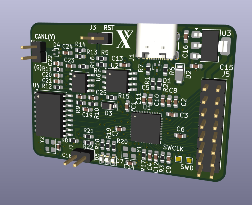
It's done! Holy... It's been a journey. Routing the end was a pain and I'm 99% sure that the 0.9mm wide power traces will be fine. I didn't quite manage to use all the capacitors for the +3V3 but it should be fine. I think I might just finish by adding a connector for a battery or external +5V input. But then I'm done! Also the beveled edges are quite nice.

Wait I just realized I need to fix the soldermask now oh dear. This'll be painful. Update: It's done. I've added a power pin for battery power, diodes to prevent overflow, and a ground pour on the top layer. All that's left is to add some decorative silkscreen and it'll be ready to ship.


2025-07-10 - Final notes (3 hours)
Fixed the +3V3 and +1V1 rails, added ESD protection, better edge.cuts
2025-07-11 - Restarting (3 hours)
Oh dear it's all bad gonna restart. Redo the differential pairs (CAN and USB), better routing.
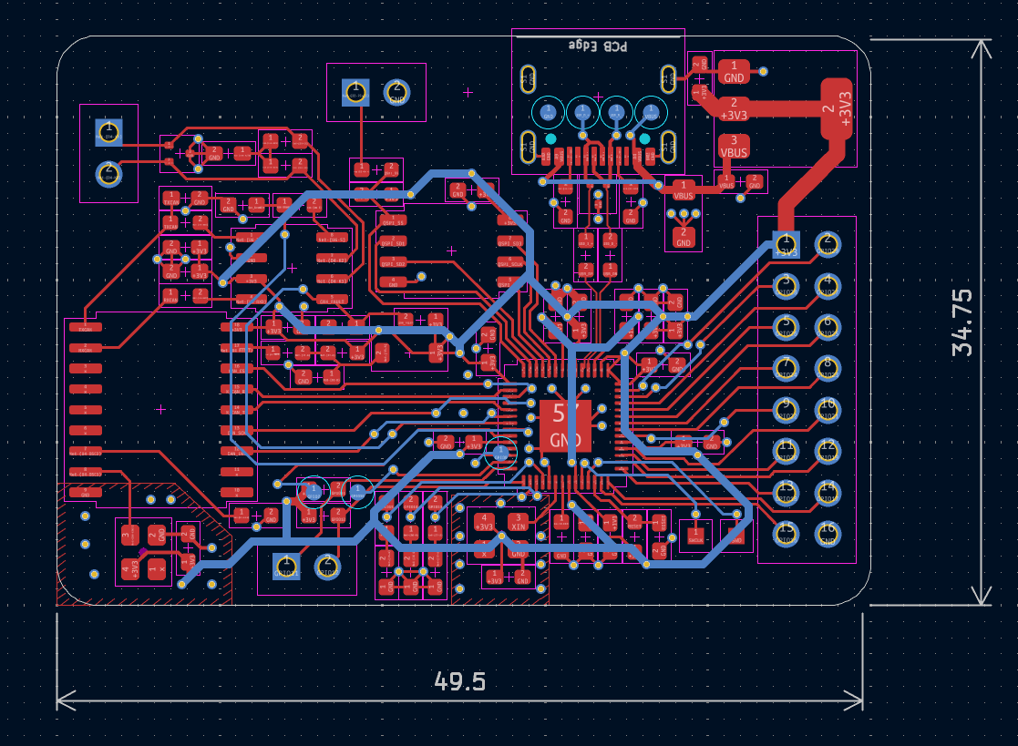
2025-07-12 - Routing gone good (13 hours)
New schematic. New pcb grouping. I'm pooped. I'm putting the SMT components closer together now to hopefully make things more efficient??
The grind never stops. Complete overhaul, new modules (using an oscillator), 4 layer board WITHIN the 50mmx50mm limits (I'm so proud of this). Inner two ground planes. Using TCAN337 instead of old CAN transciever. ESD protection on USB datalines, VBUS and CAN headers. I'm so tired.
2025-07-13 - Case (2 hours)
Added a case