
CYBERPAD-01
3 key, cyberpunk inspired macropad with backlight and a rotary encoder
Total Time Spent on This Project: 29 Hours
Day 1 - PCB - 5 Hours - Jun 30th
The Cyber Pad is going to be an extremely futuristic looking macropad.
It's going to be a test of my design skills and just a fun side project I want to build.
I really like the cyberpunk aesthetic and want to make a series of projects that go with the theme, maybe ending up with a cyberpunk themed 3D printer.
Anyways first I'm going to do some drawing and brainstorming on how I want this thing to look.
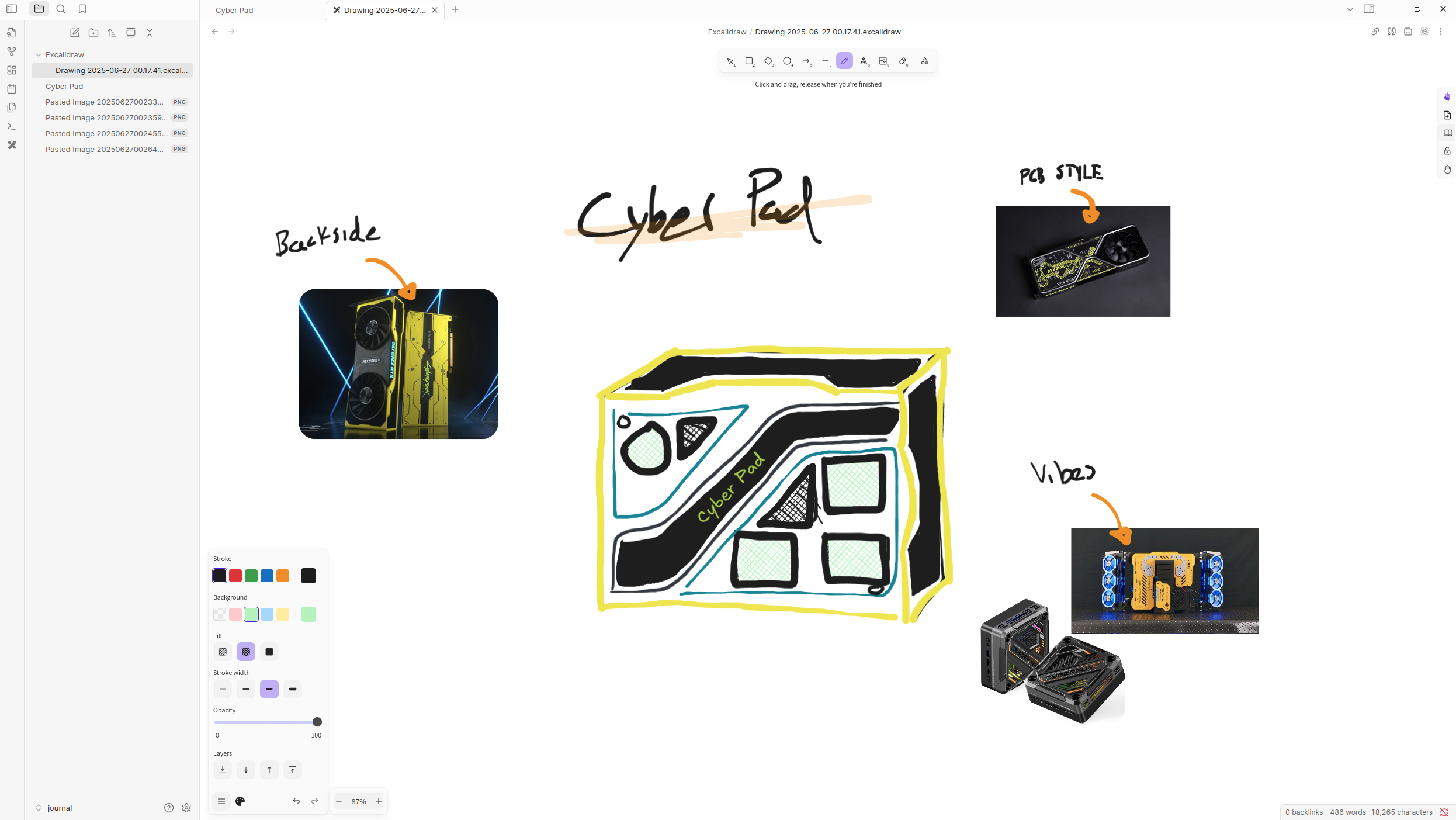
Anyways this is my main inspiration that I spent some time on, I really like the buttons like this so I think I'm going to leave it like that. I don't want any OLED's or anything because I feel like that ruins the vibe so I'm going simple with a major focus on the design.
Also this design seems quite blocky but the actual thing will be nice and round.
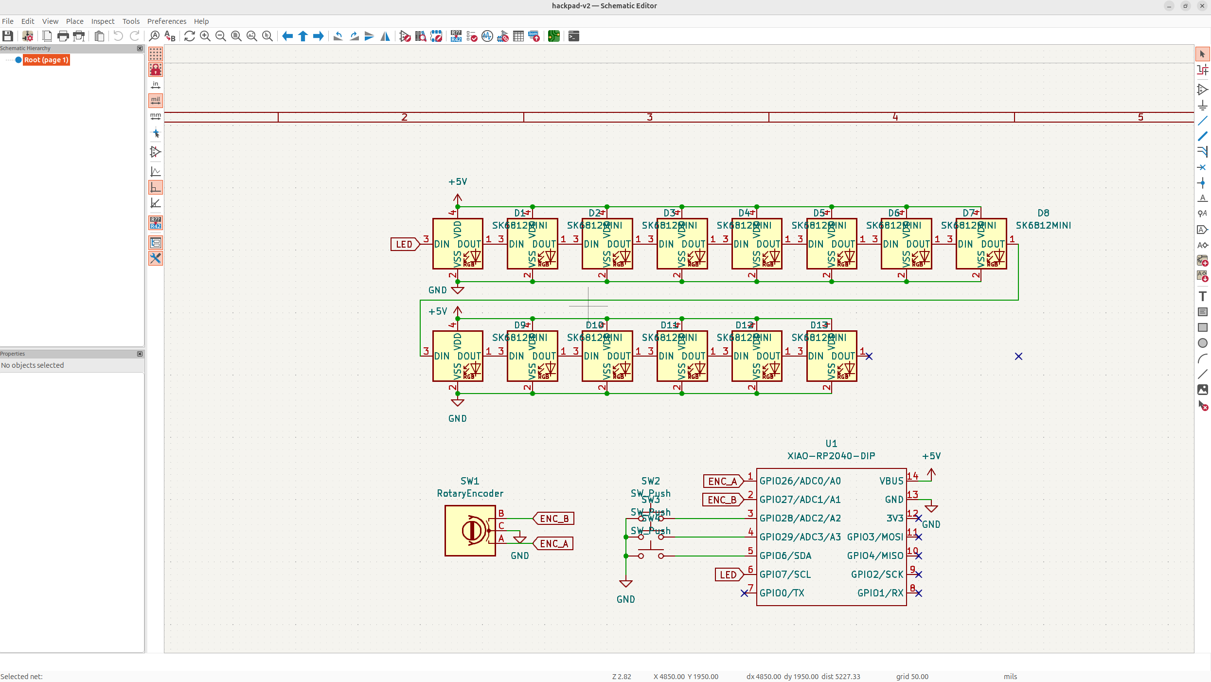
Now let's whip up a quick schematic. I'm trying to stick to best practices possible and I'm going to do the neopixels once I'm done my case!
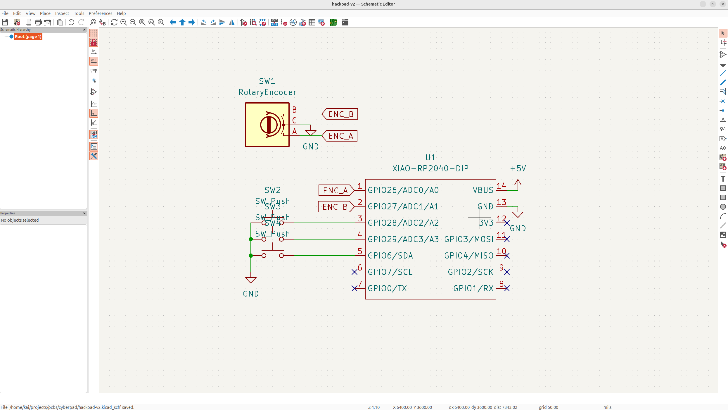
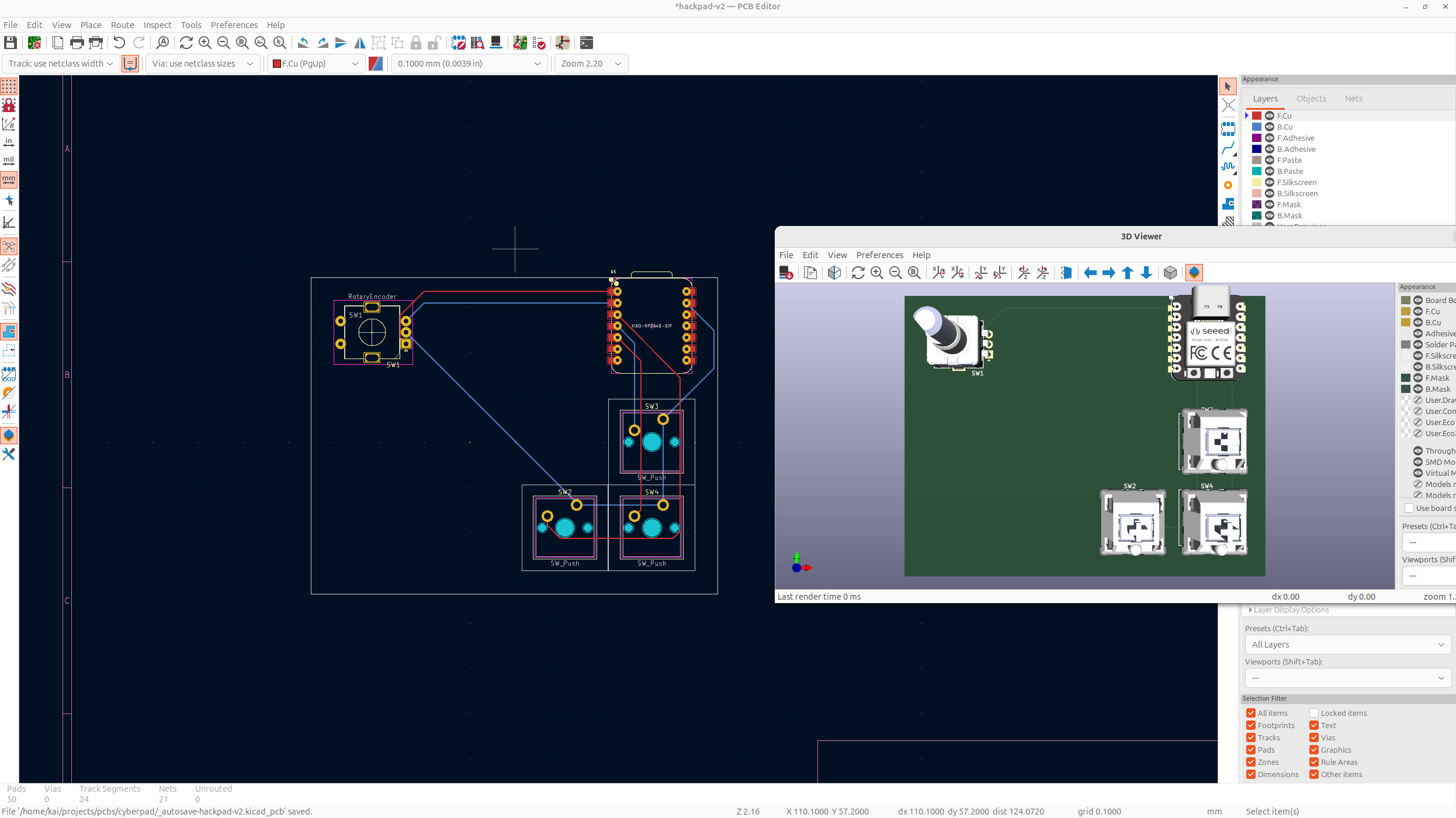
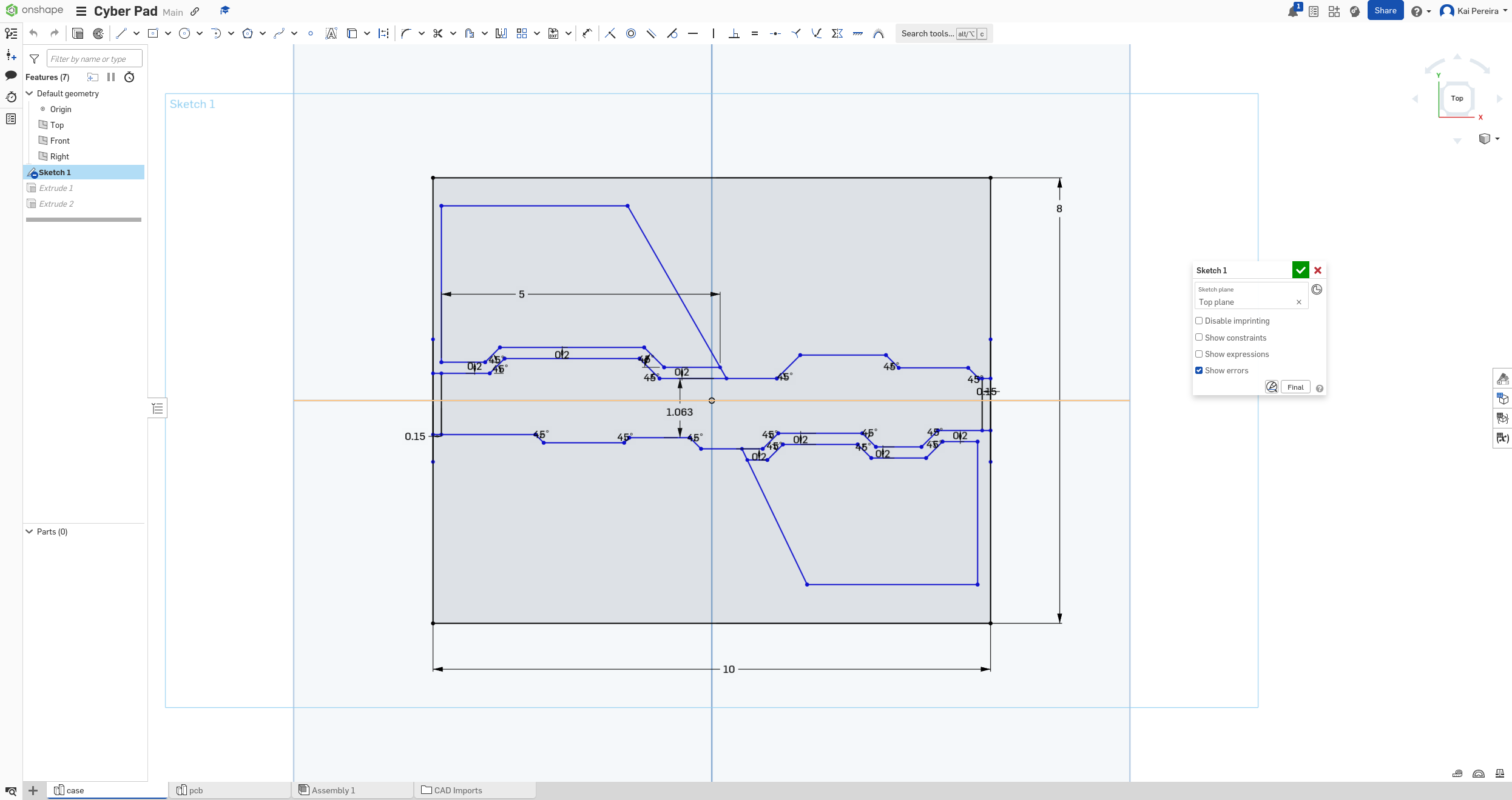
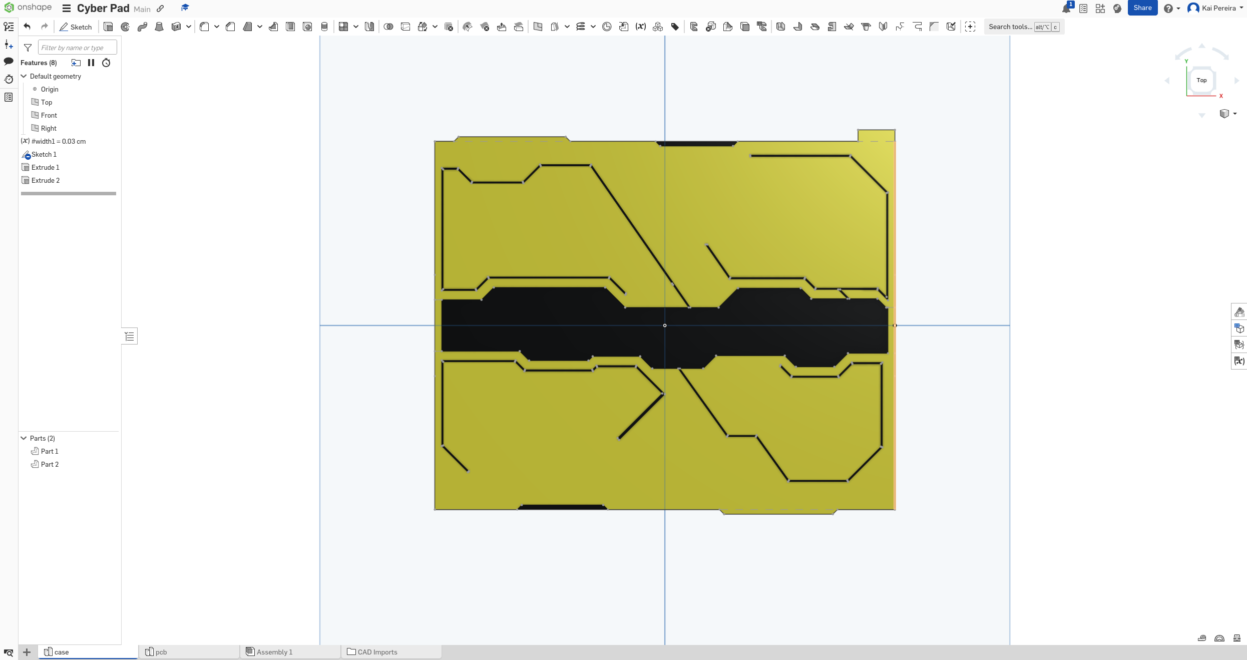
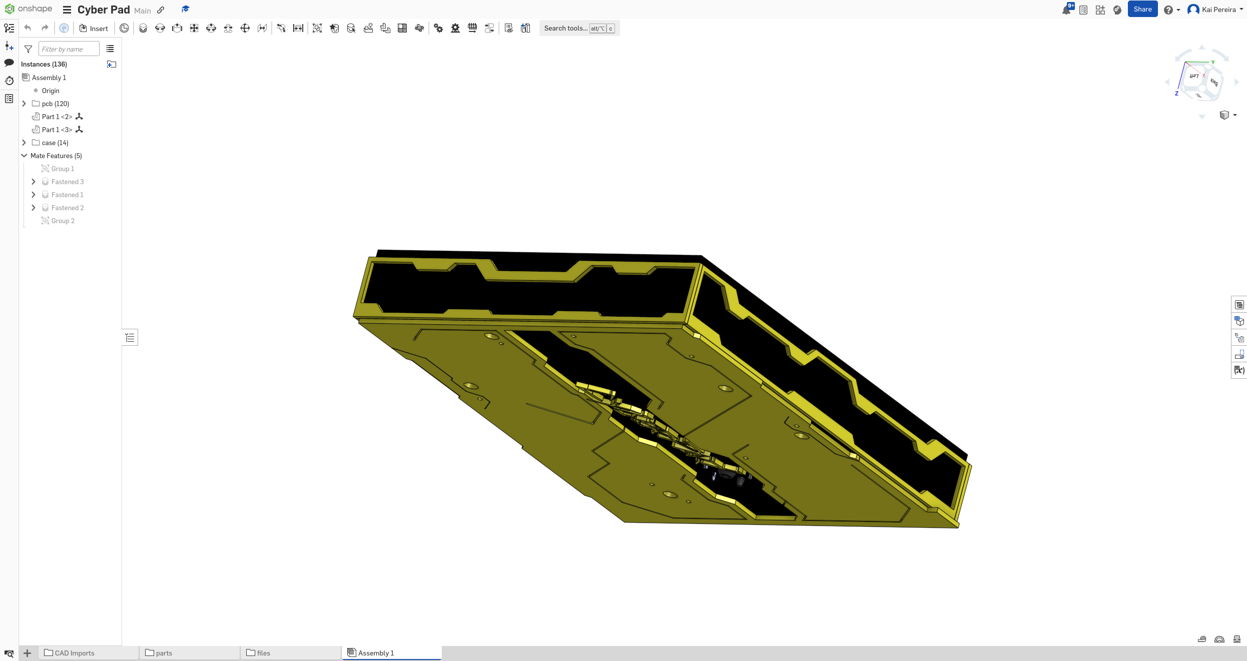
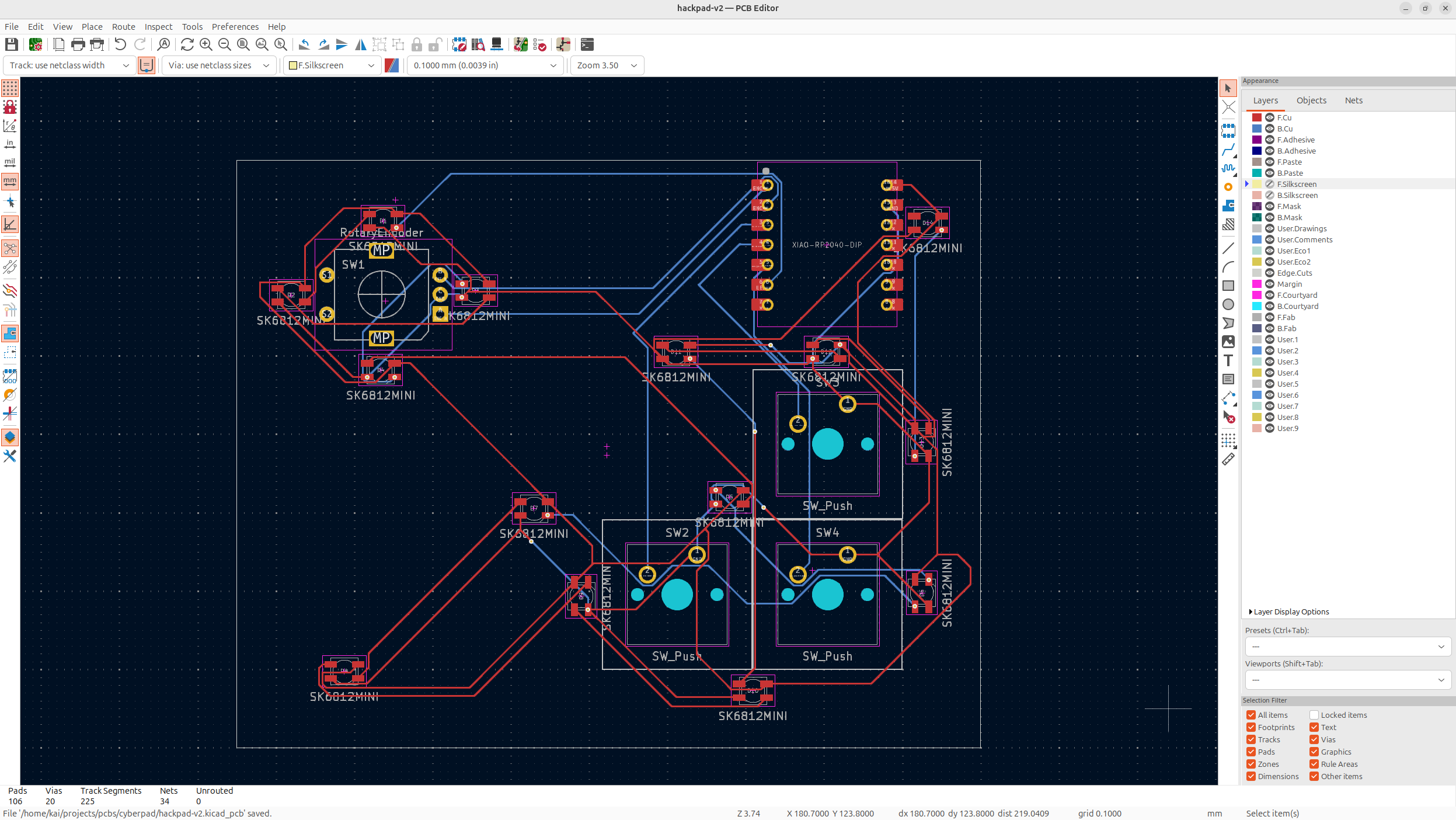
Now time to do the PCB, took me quite a long time because I was figuring out some footprint and alignment stuff.
Day 2 - Case - 8 Hours
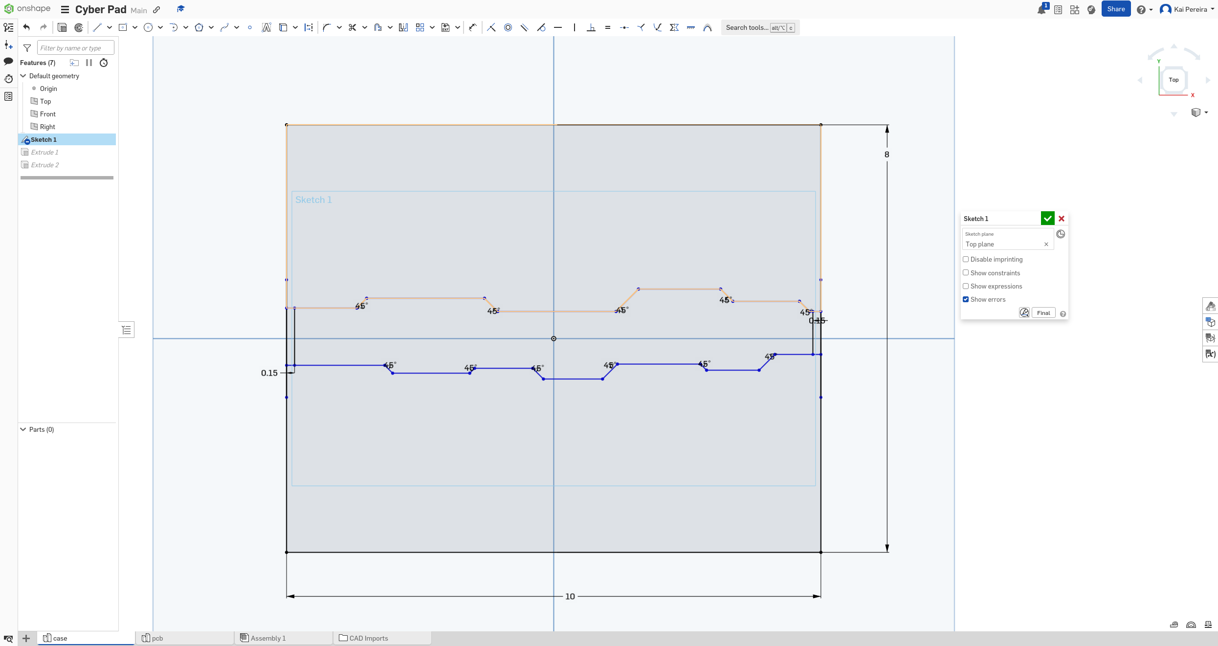
Now I'm going to start modelling the case, I'm going to give about 1cm total on each side just as a placeholder and then I'm going to model the main interior of the bottom I want to go for.
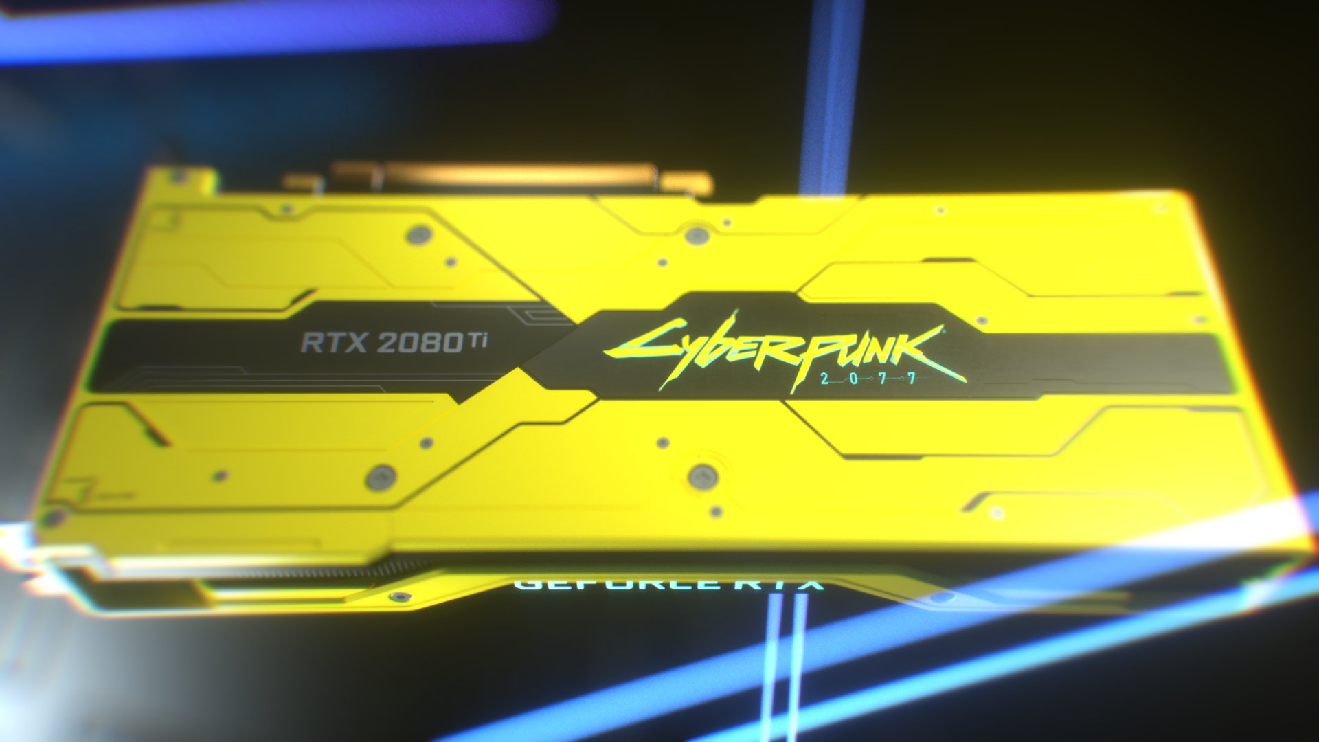
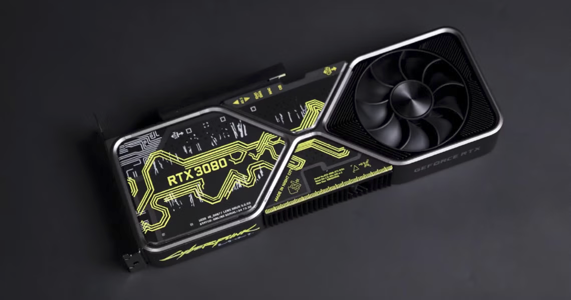
Now that I have this base, I'm going to add some designs along the side. I like the way the graphics card is done, so I'm going to do something similar to that.
Now I kind of want to go with a polarizing like effect which will go with the top of my case:
Now I kind of want to with with some other designs just to fill the space, I'll look into the graphics card design a bit more and kind of go off that. And now I have a really col base to go off of:
Now I'm going to make the shapes a bit more complicated to give it some detail. Now it's looking sick.
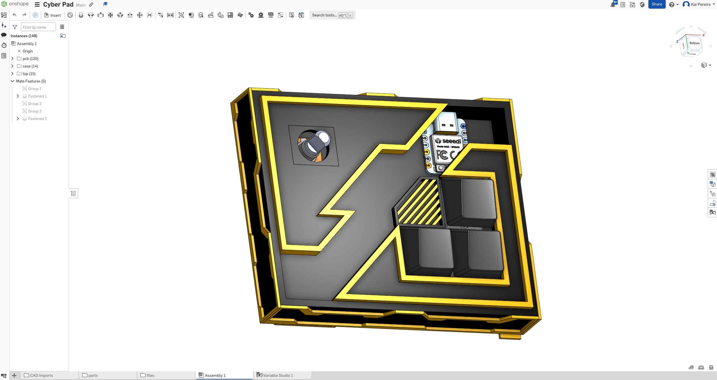
Now I really like this style where there's details on the top and bottom, and circles where all the divits are, so I'm going to first add the cool bottom and top details.
And the minor details are really starting to add up.
Now I want some of those extra thin lines. It's starting to look incredible!
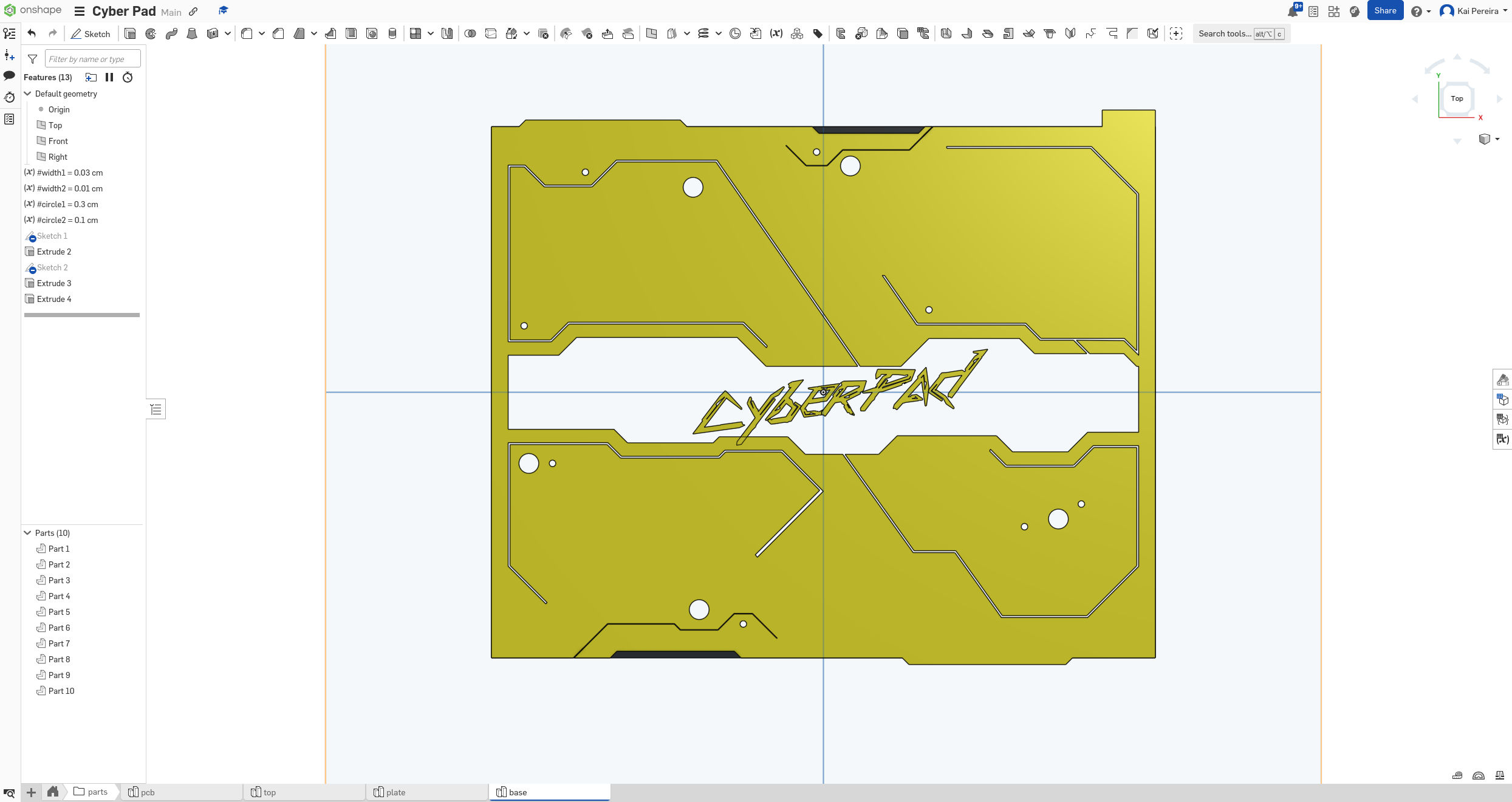
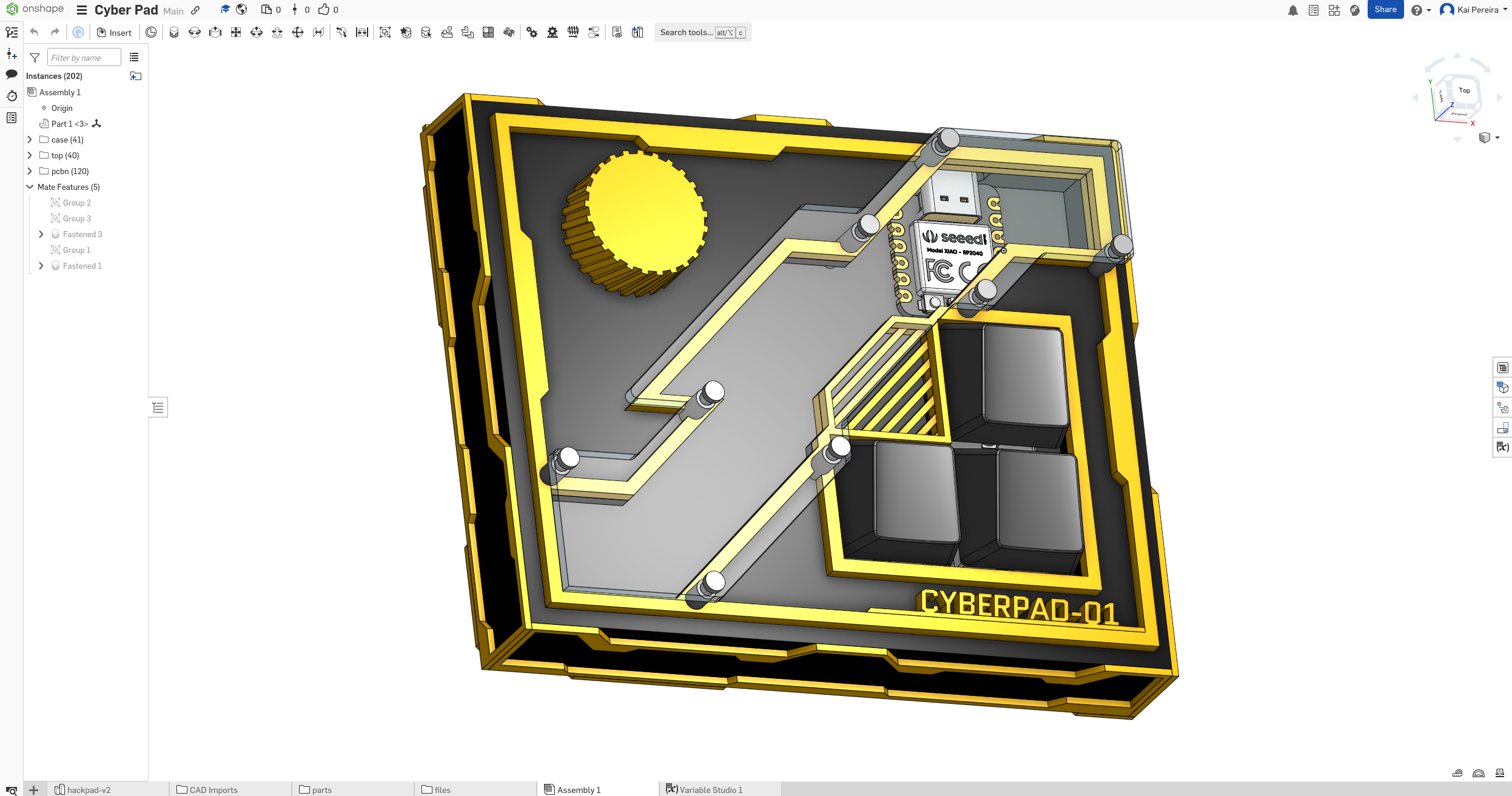
Next I added the circles and the logo. The logo is done in inkscape with the Cynata font.
Next I added some walls to it, and then created the plate and top plate.
Now I'm going to start working on the side designs. I want them to be pretty similar to the GPU design and then make the top like the PC.
Anyways next I added the side designs, I've mirrored each side onto the other side for simplicity and it's looking even better now!
Now I kind of have to figure out what I want to do for the top. I really like this style and kind of want to go for something similar.
I might actually play around with my hackpad colors too, maybe a different color would look better like this green or something. Anyways next I'm going to work on the top. I don't actually have anything in mind, so I'm just going to kind of stick to the same style for now and add more detail later.
And that looks fitting but still now exactly what I want. I really want to see what it would look like if I put a piece of acrylic over the gap now.
This took a long time and I'm sorry I didn't journal all of it, but I added a knob, the acrylic and some text on the bottom. Looking absolutely insane now.
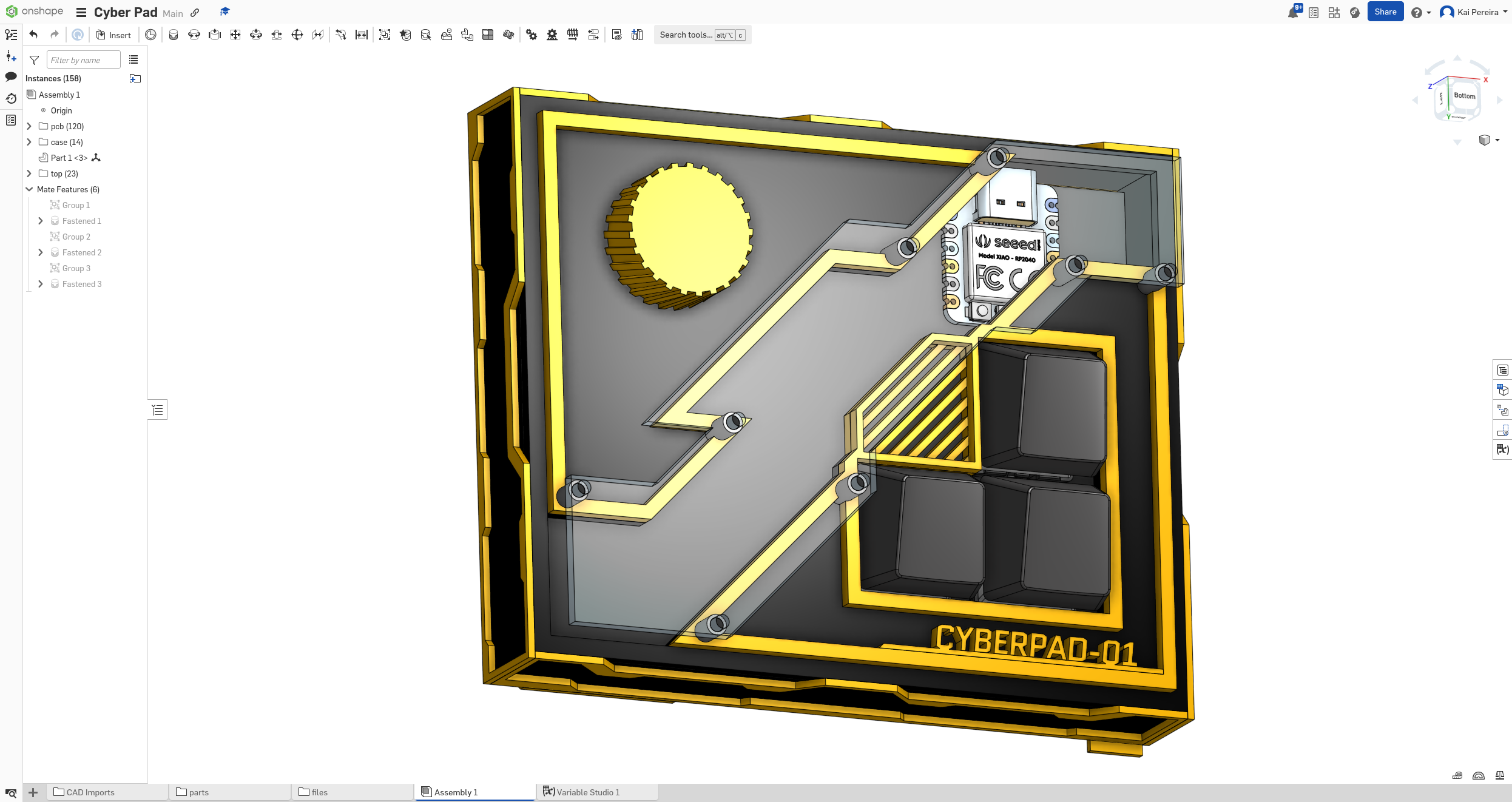
But we are not finished, nowhere near the craziness I want. Next I'm going to add all the extra little things to give it dimension.
I also refined the design a bit so it's easier to print and it looks pretty good.
Day 3 - Refining the PCB and Case - 4 Hours
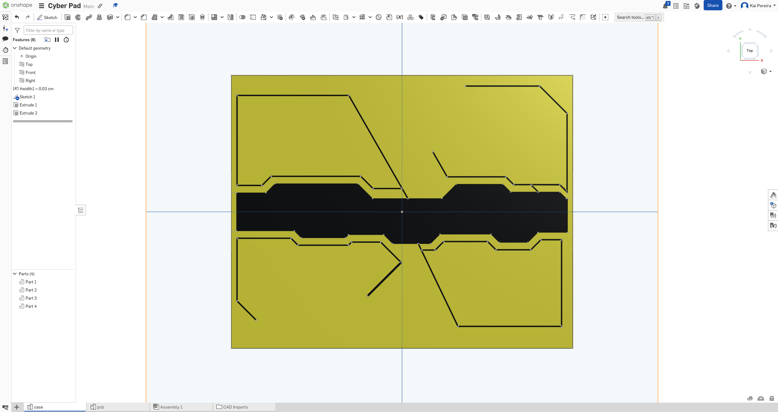
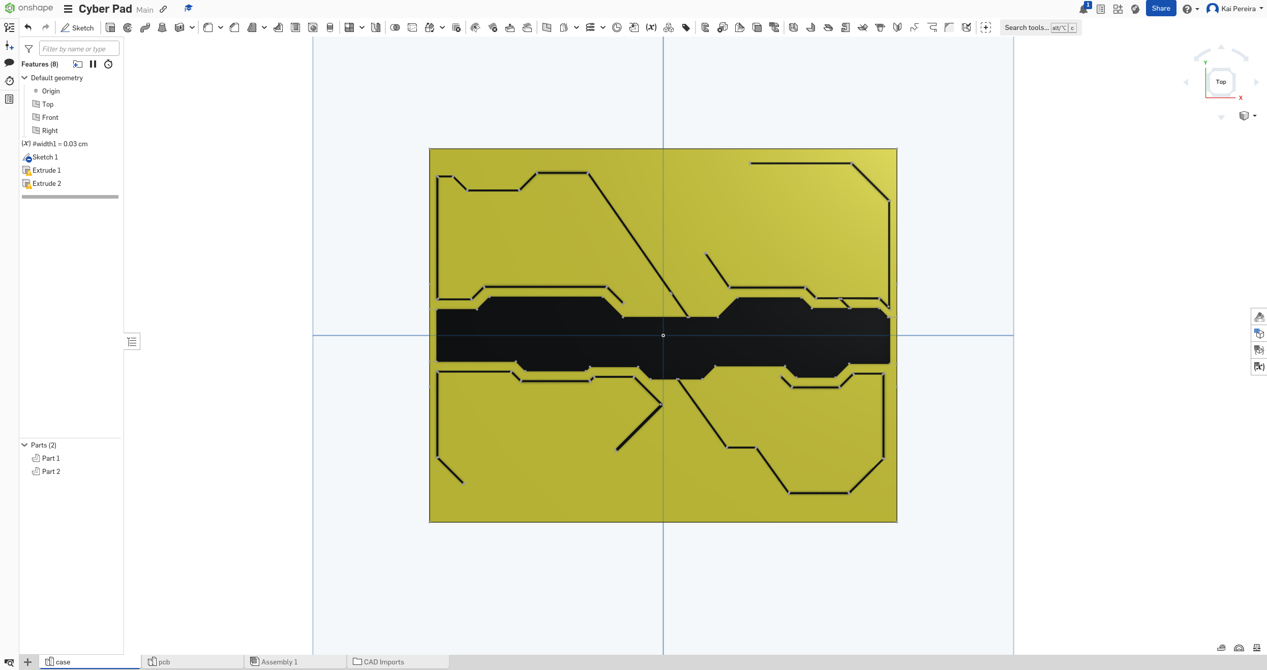
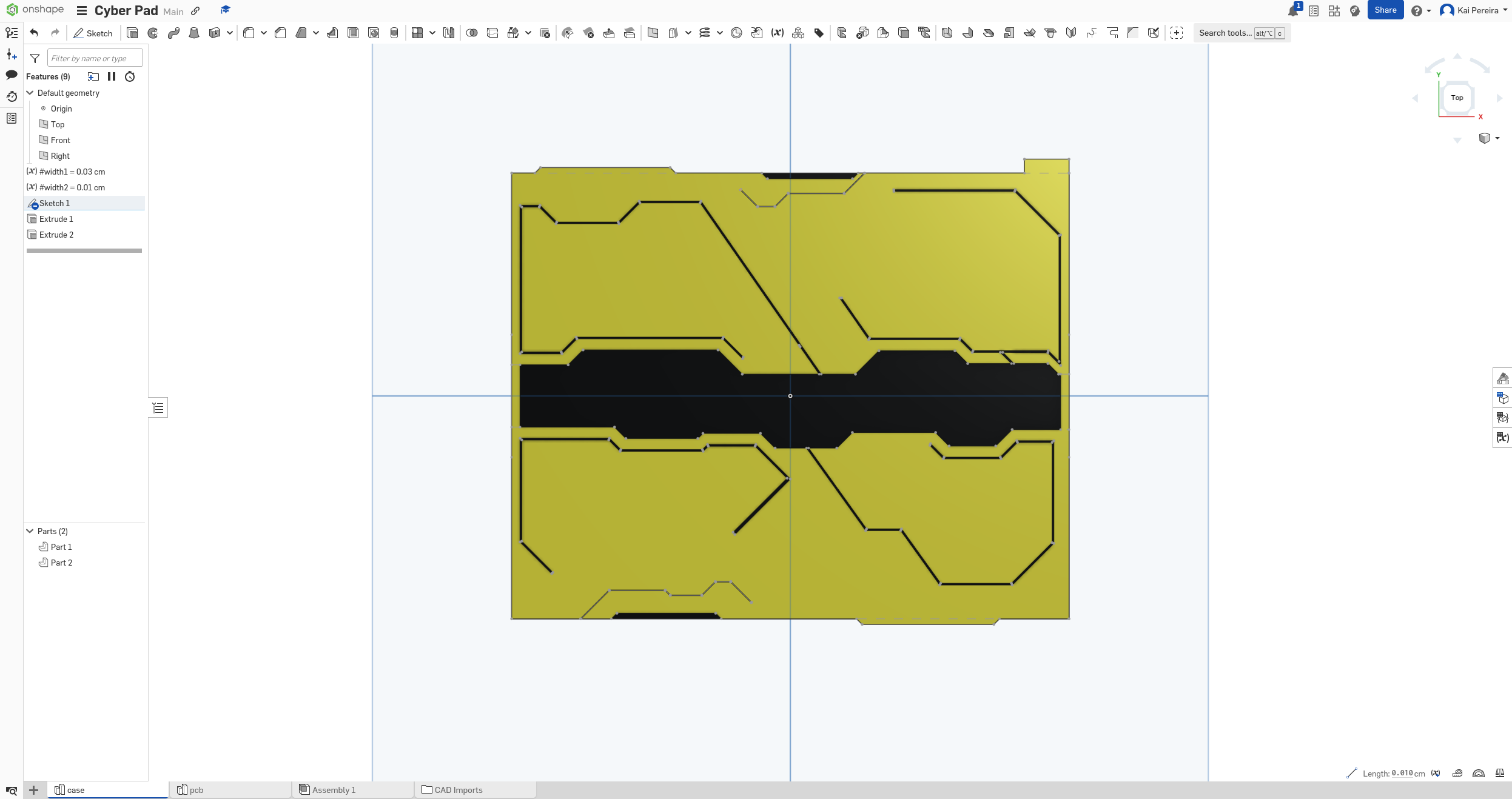
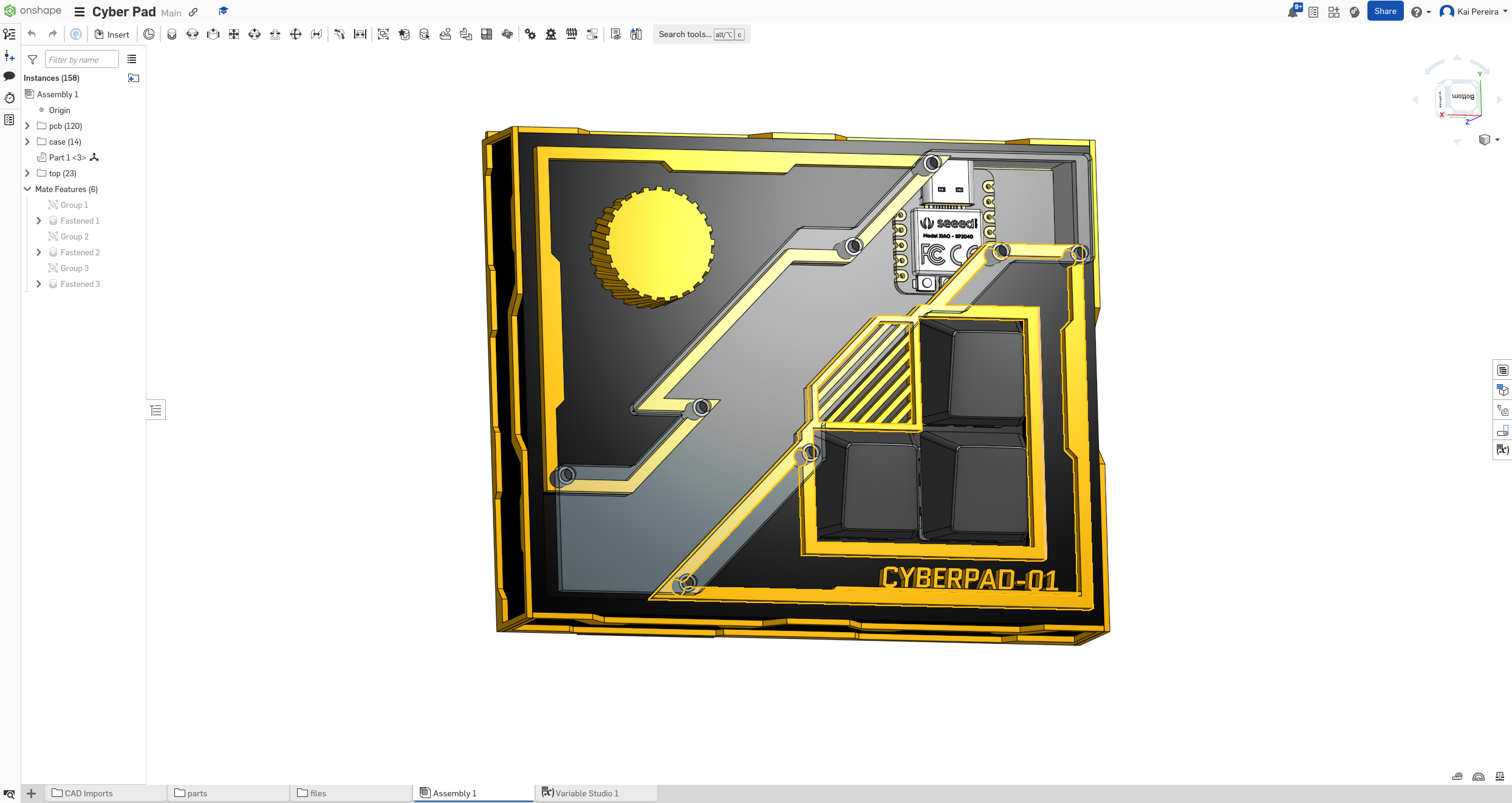
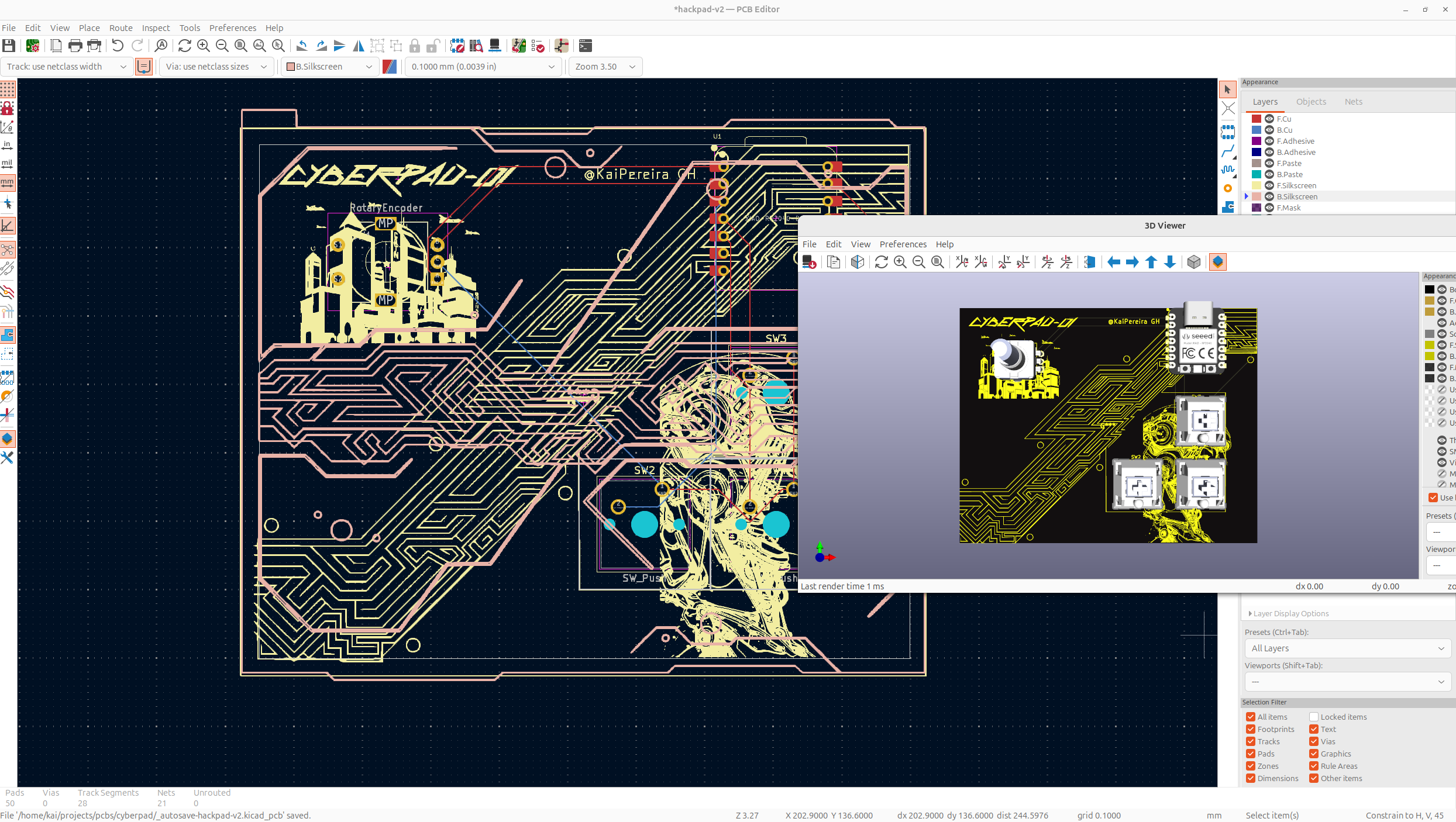
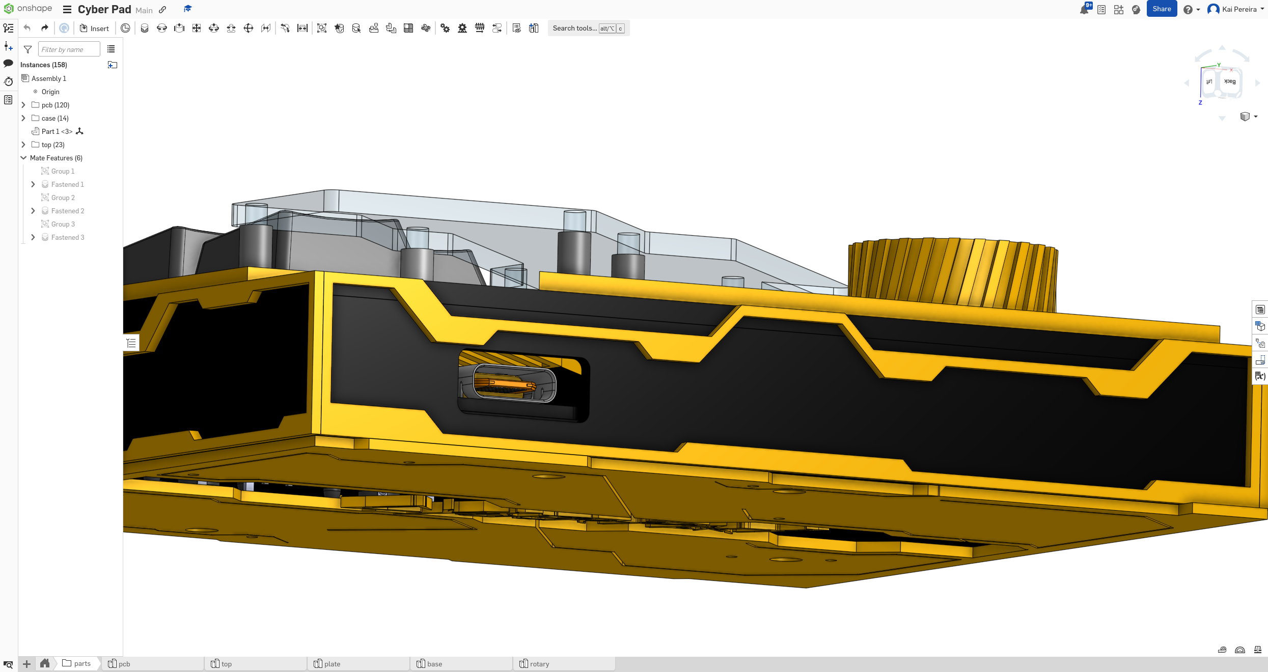
Next I need to customize the PCB so that it looks rlly cool inside of the case. I wanna go for like exposed trace with cyberpunk drawings style. I used the case DXF as a reference point, and then used figma to draw the lines. Then I just add the image properly scaled to kicad.
Now I completely forgot to add the neopixels so let me do that real quick.
Rewired + new schematic.
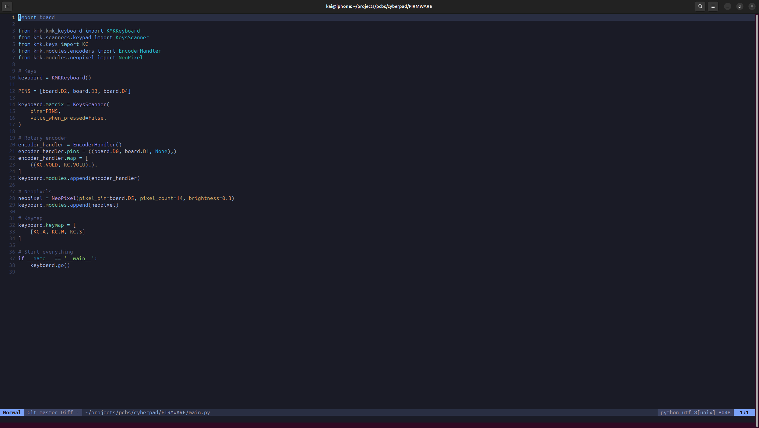
Next I did the firmware. It was really simple, just some python with KMK.
Next I completely forgot but I needed a USB port so I added that in.
Then I'll just add the bolt heads and such, and we're done with the case!
Day 4 - Rendering - 6 Hours
Now I've never used Blender before, but I really want to render my case and PCB. But before that, I have to update my KiCad! And it may have taken me way too long, but after 2 hours, I've updated KiCad.
Now I can export the PCB with silkscreen (brand new feature!!) and add it to blender alongside my case.
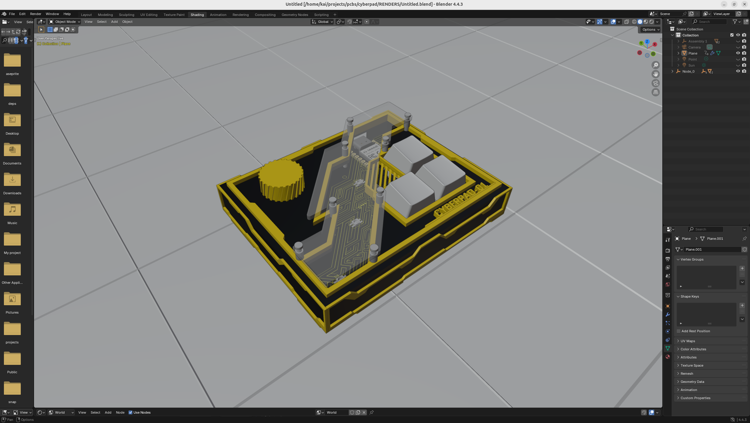
I've also added this cool blueprint effect on the plane I've put my model on which will look really futuristic in the render. To do this, I just used a wireframe on the plane and then gave them 2 different meshes. Now all this stuff took way longer than I'm making it seem but yeah that's basically what I did.
Next I added all the meshes and rendered everything, I couldn't figure out lighting so I may or may not have just used the photo's from the render without light.
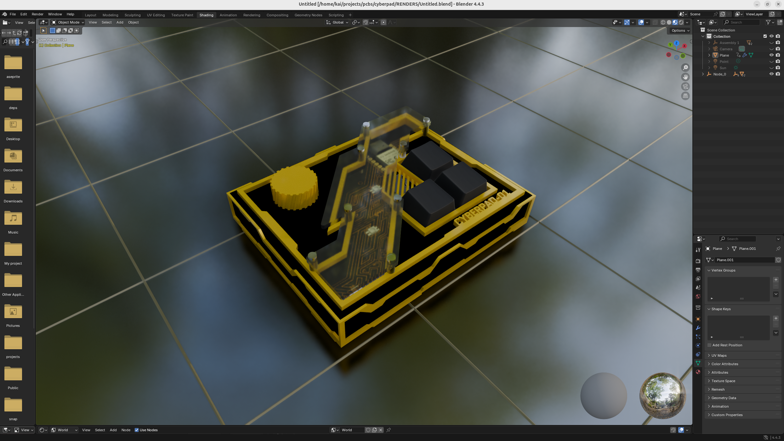
And there's our render completed!
Day 5 - GitHub Shenanigans - 2 Hours
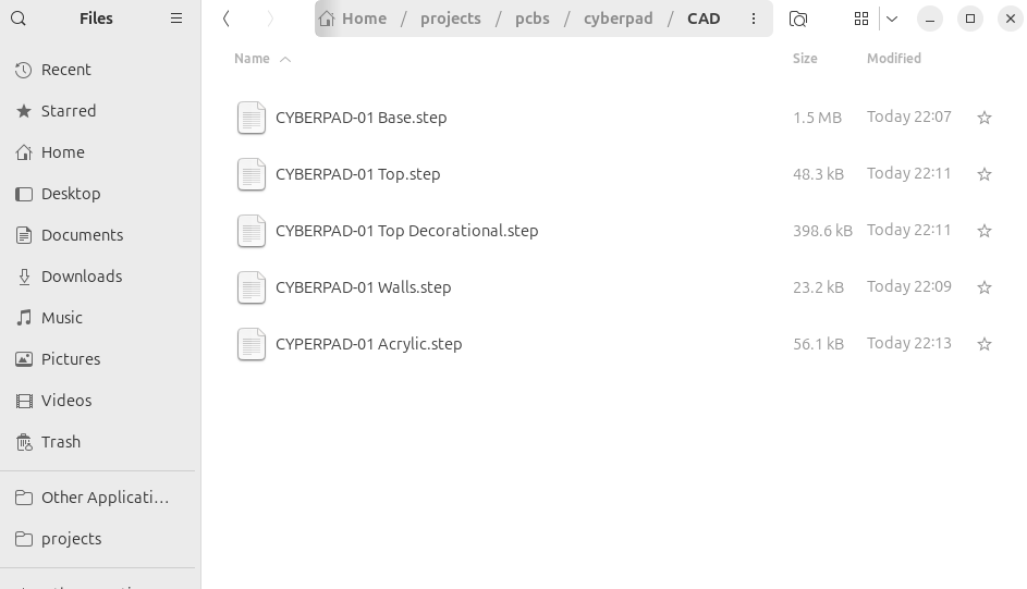
Now I needed to add all of this to GitHub, I left everything pretty organized so it won't be too much of a hassle! I pretty much have everything in there except for the production files so let's add those!
First I'm going to add all my CAD files, I'm going to put all the separate files I need to 3D print, I have to separate all of the different parts to 3D print, but it's not too complicated so I got through with relative ease.
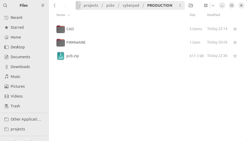
Next I need the production files, all the files I need to actually make my PCB. This is just the: - All PCB gerbers, drills, pick and place, etc. - All 3D printed parts - All firmware
So I just moved my CAD folder into this new one, move the firmware file, and then made a ZIP file with all the gerbers and stuff.
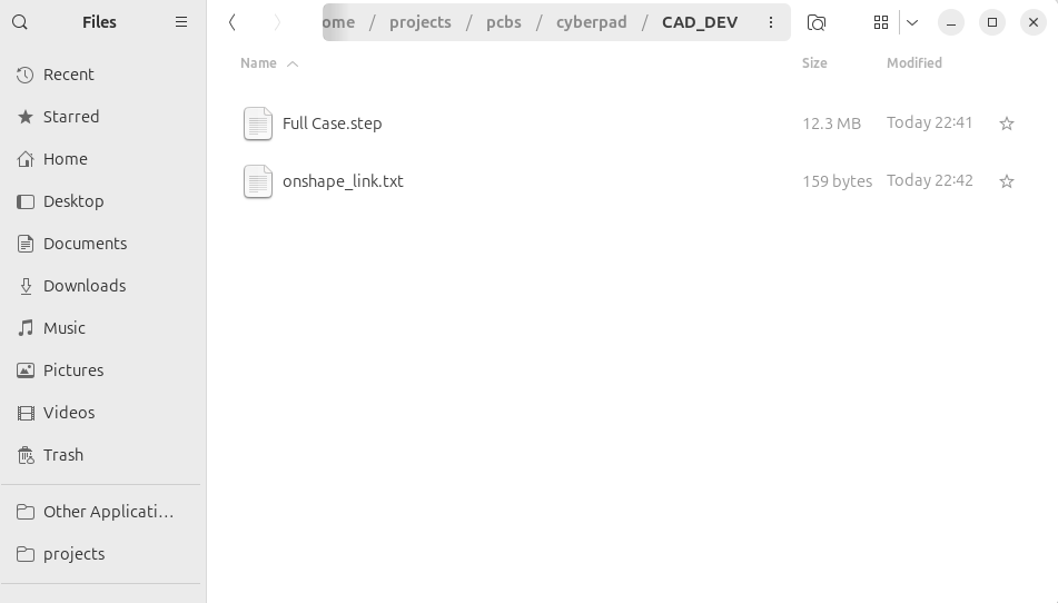
And then finally, I had to add a new CAD folder with just my full case and then I also added my Onshape link as a txt just for the people that are looking there. And that is actually everything!
Day 6 - Soldering and Case - 4 Hours
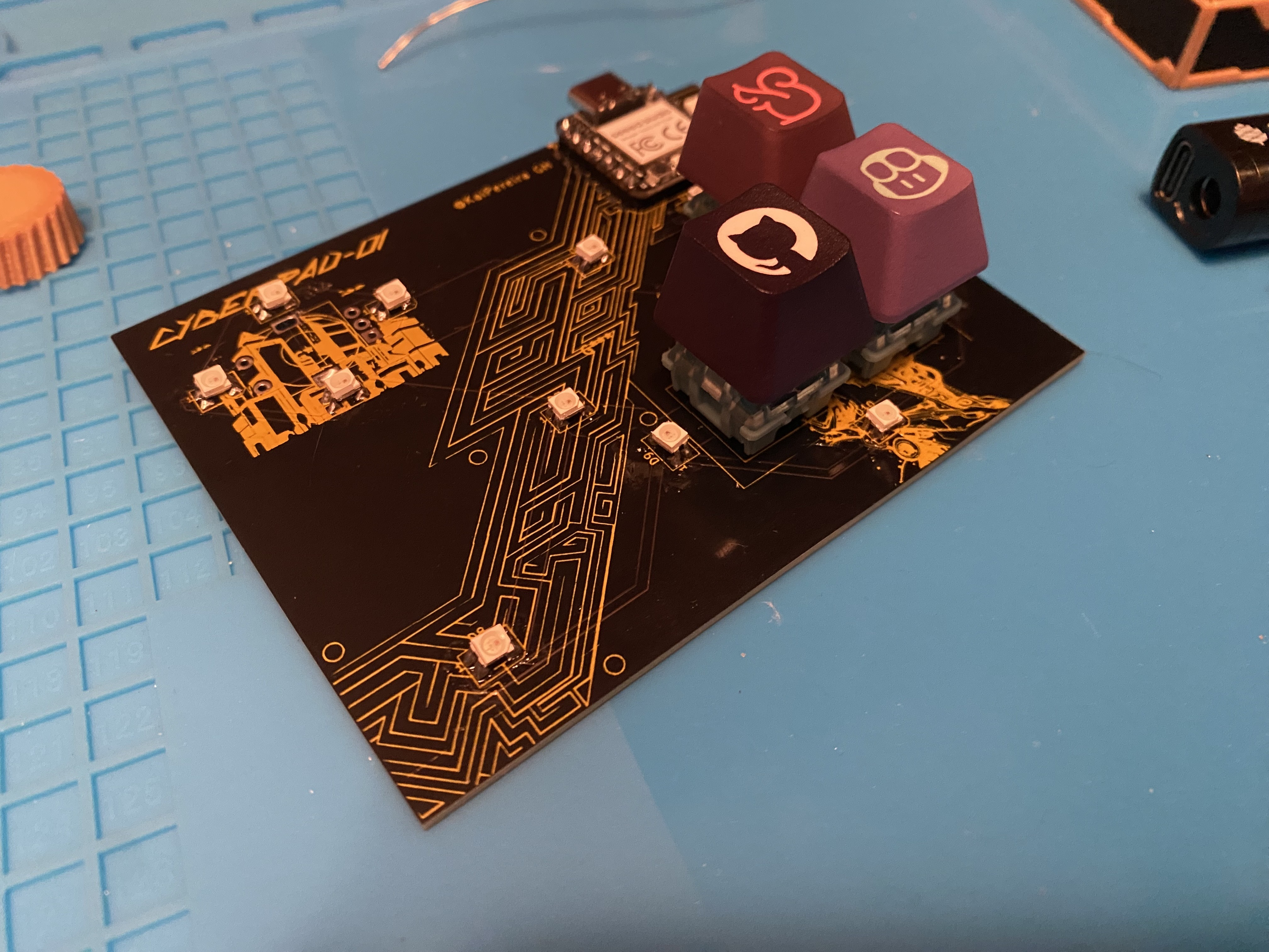
I like to order my days chronologically, but a couple weeks have passed! Now I've receive my boards and just have to solder them and assemble it. So first things first, I whipped out all the soldering stuff.
I like to use my trusty pinecil with resin core leaded solder and then I use some wire cutters to cut off the strands.
Something I learned about doing the neopixels, especially SMD like this, is to tin the pads, and then bend the leads so that they touch all the pads, and then just touch the solder to the pads, works very nicely.
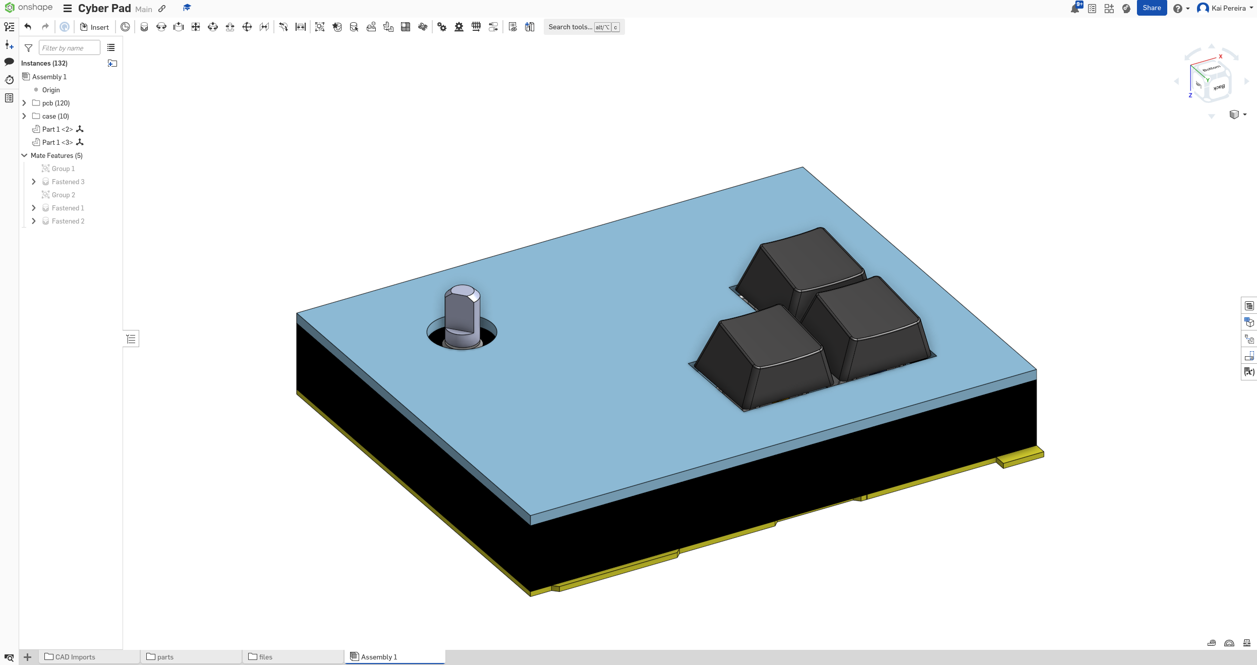
Anyways, the boards turned out very nice, and then I added some github keycaps onto them.
Next I needed to assemble the case. I just glued the walls onto the sides nicely, and then I actually forgot to get the top part of my case printed, so I used duck tape to like hold it in place, and I feel like it turned out pretty nice.
I skipped on the acrylic for now, but all stuff I need to do when I get back from my vacation:
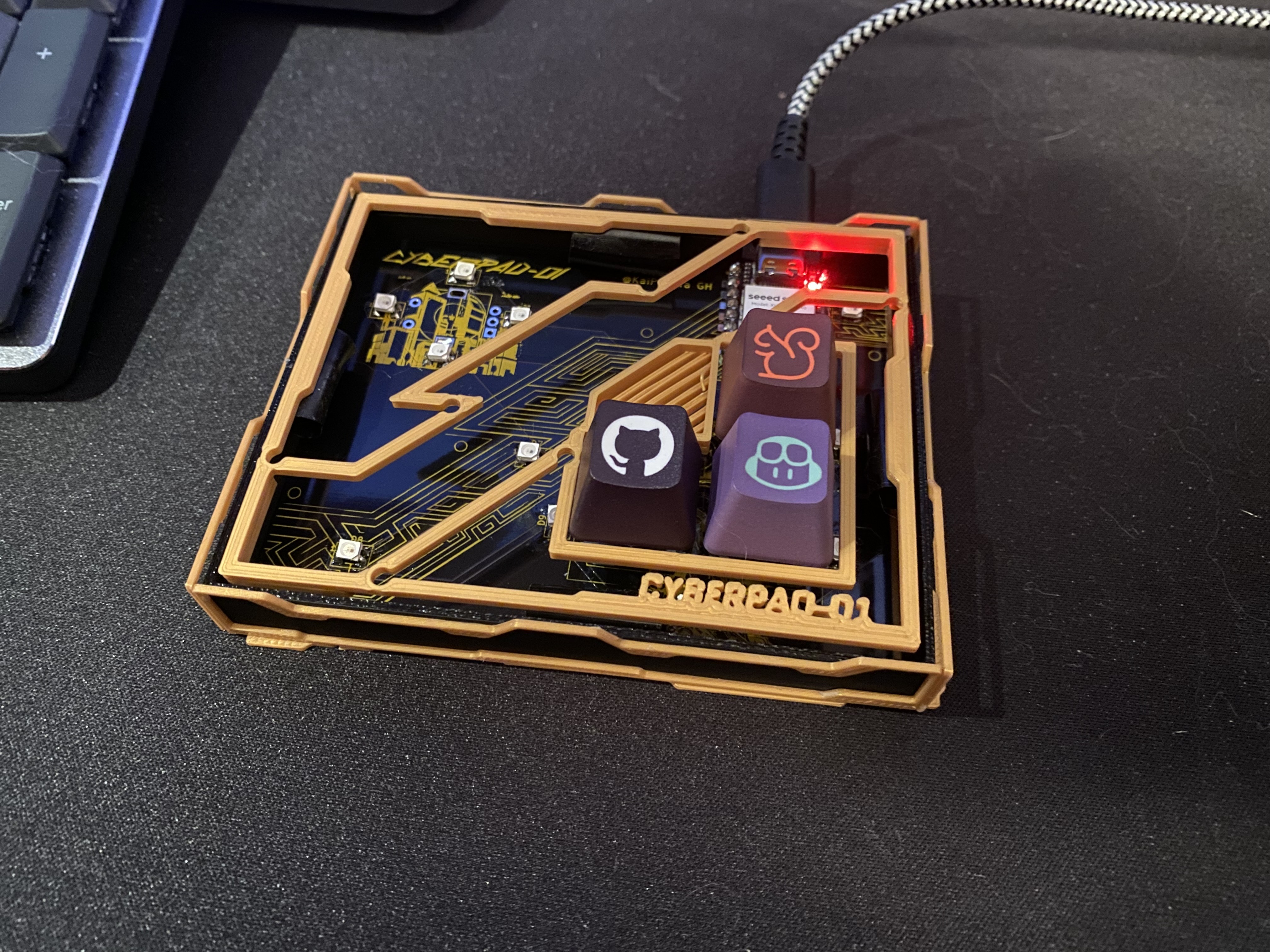
And then I just simply uploaded my code, and booted up the XIAO using the UF2 from the circuit python website, and it was ready to go!
I'm a bit sad I didn't get the neopixels to work in time for my trip, but I'll get them working eventually!