
VocaLink
DIY mouth tracking for VR avatars, bringing your real expressions into virtual worlds. Built on Project Babble.
Total Design Hours: 35h Total Build Hours: 10h
2025-07-09 - More expressions!!!!!
I play VRChat... 🗑️😱🤯
I know I know, very crazy social platform but once you find the right friend group, it's a great way to socialise. I want to express myself more in VR. I've already got full body tracking ✅, but facial expression ❌. Tracking the eye and face, lets see how other peeps have done it.
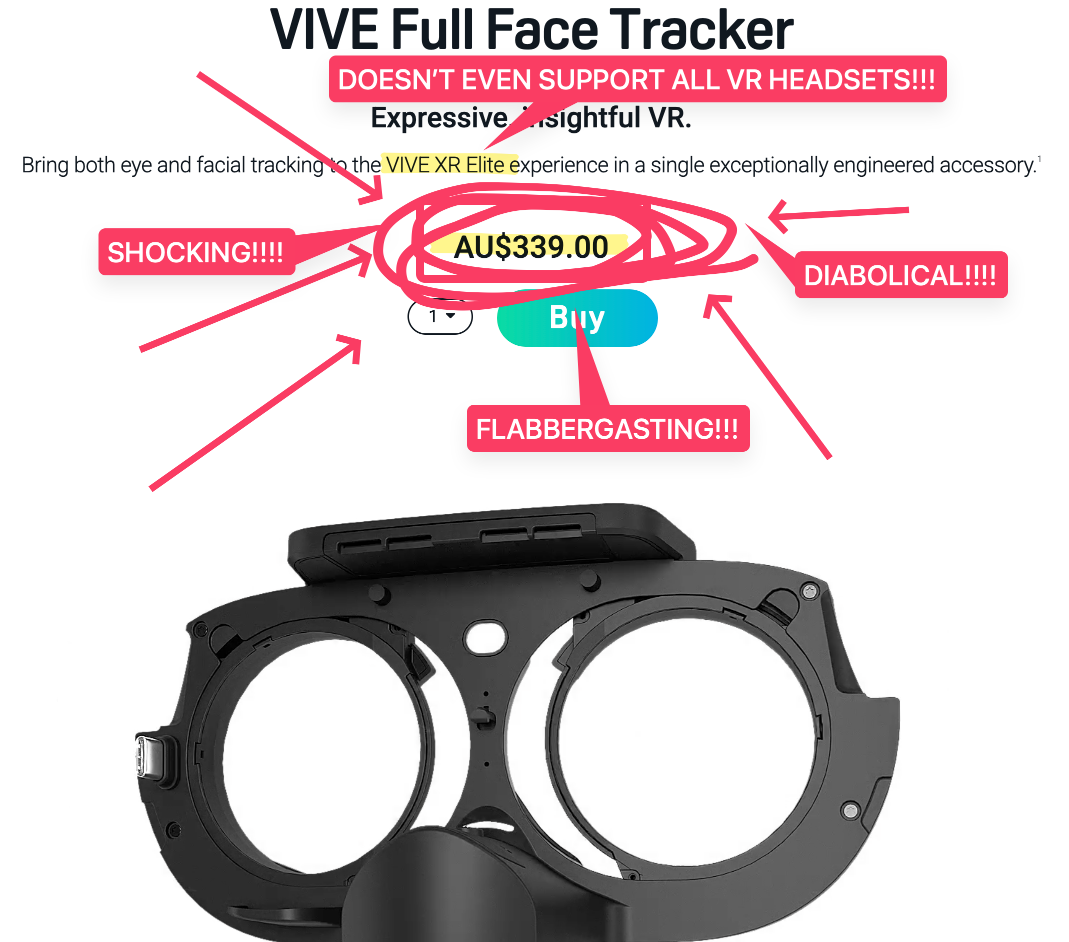
Yeah no thank you 🙂↔️. So it's time to DIY it! I decided that I won't be making an eye tracker and will just focus on the mouth tracking aspect. Why? Because eye trackers need IR LEDs and I would not like to risk getting blindness.
Some research led to Babble, a Source First
mouth tracking solution. They provide the firmware and machine learning model whilst also providing a guide showing how to use a Xiao ESP32 Sense with an OV2640 and some IR LEDs... but that sounds too easy so I'm going to use a bare ESP32 chip and make it all on one PCB.
Time Spent: 1 hour
2025-07-10 - Schematic creation
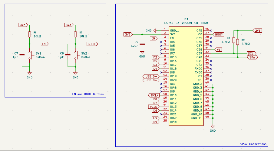
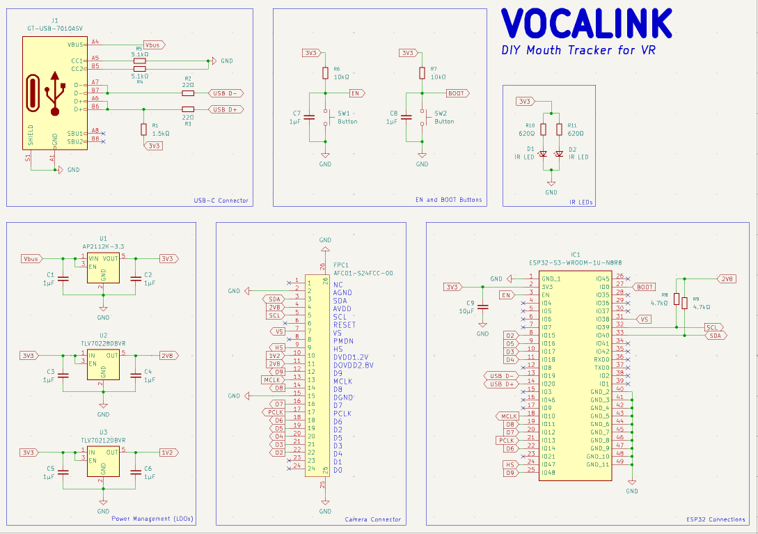
Today is the day before I travel to Undercity so it's time to speedrun the schematic. I decided to go with the ESP32-S3-WROOM-1U-N8R8 as the brains since it has in-built RAM and it uses an external antenna. The camera will be the OV2640 as it is the one recommended by Babble. It has a high FOV and is an IR camera. The IR LEDs brightening up my mouth will be the XL-3216HIRC-850. They are unfocused 3.3V 850mn IR emitters. This in combination with 620ohm resistors should result it in having around 9% of the safe limit of IR exposure to the eyes. Even though they are not directly pointed to the eyes like eye trackers, they will be extremely close to my face so I would not like to take any risks. The connector will be USB-C obviously.
Let's talk about power management now. Very not fun... power go through USB-C port, supplying the standard 5V Vbus, which is then directed to the AP2112K-3.3, an LDO regulator which steps down the voltage from 5V to 3.3V. For the specific voltage requirements of 2.8V and 1.2V, I have another two LDOs, TLV70228DBVR for 2.8V and TLV70212DBVR for 1.2V. They each have an input and output capacitor to ensure voltage stability and filtering out noise.
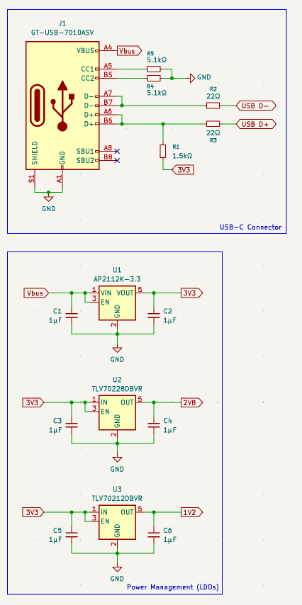
Now some stuff for the microcontroller: The USB lines are connected to the ESP32's internal USB peripheral magical thingys. Then I have SW1 and SW2. One for ENABLE (EN), acting as the reset button and then one for BOOT, for... you know... booting the device.
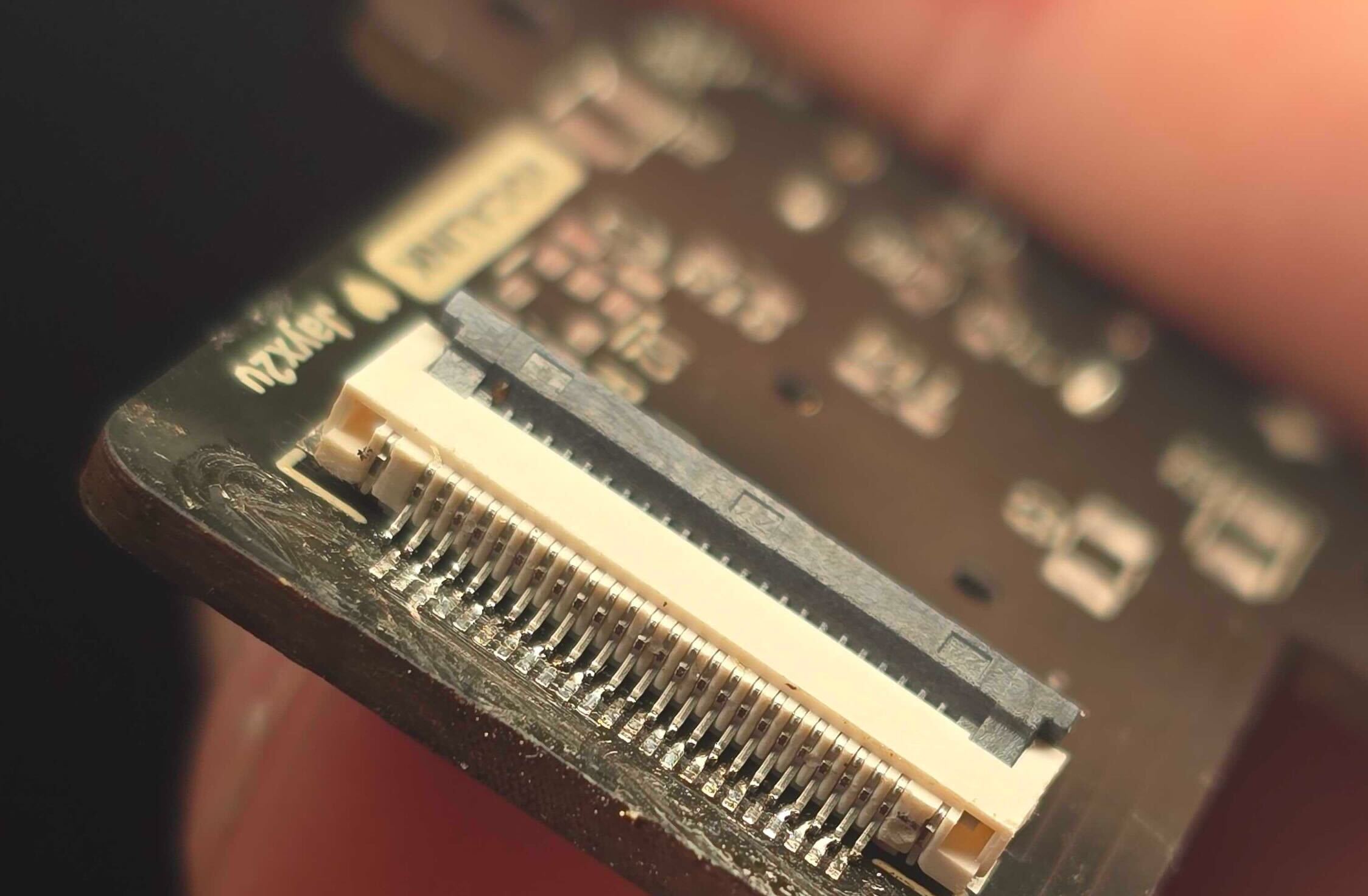
Next is the camera and lighting. To connect the camera to the microcontroller, I added a 24-pin FPC connector. This connector breaks out all necessary signals: the 2.8V and 1.2V power rails generated by our LDOs, I2C communication lines (SCL and SDA) for camera configuration, and a parallel 8-bit data bus (D0-D7) for image data transfer. Clocking signals like PCLK, MCLK, HS, and VS are also routed from the ESP32 to this connector to synchronize data capture. To help the camera see and brighten up the area underneath the VR headset (which is where the camera will be located), two IR LEDs will be placed.
And with that, here is the schematic in all its glory:
Time Spent: 13h
2025-07-16 - Post-Undercity depression
Hi. It's me. You should go on a side-quest and see what my team made at Undercity! Made it into the Top 10: Blind Defusal. Currently at a 22hr layover so it's time to speedrun the PCB!!!111!!11!! ._.
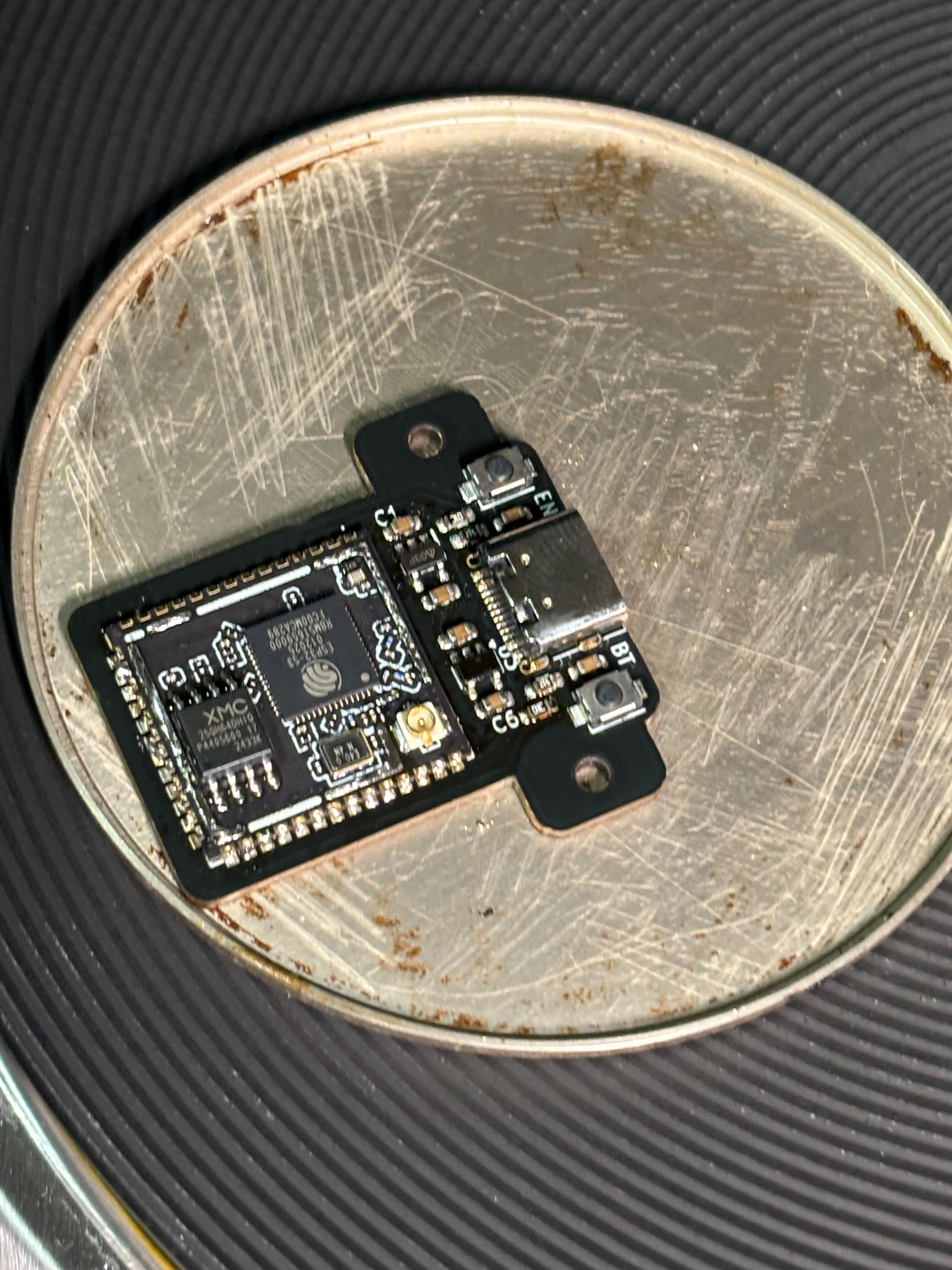
On the front layer, we got the control deck.
Got the big brain ESP32 with the USC-C connector at the top. Positioned very nicely so the cable can be firmly attached with the mount and cleanly around the VR headset. Go the two button there also for easy access.
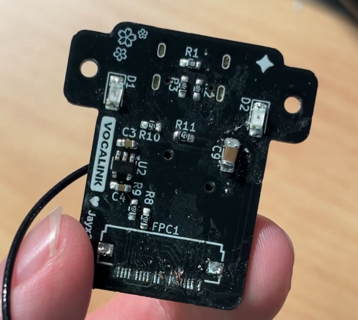
The back layer is the eyes of the deck. I got mainly the very big 24-pin FPC connector here and the IR LEDs on the sides for ample lighting. Hopefully the ground planes help with heat dissipation???
The main time waster here is going to be making the PCB footprint as small as possible. PCB tracing is art, and this is definitely some fine art. 🤭
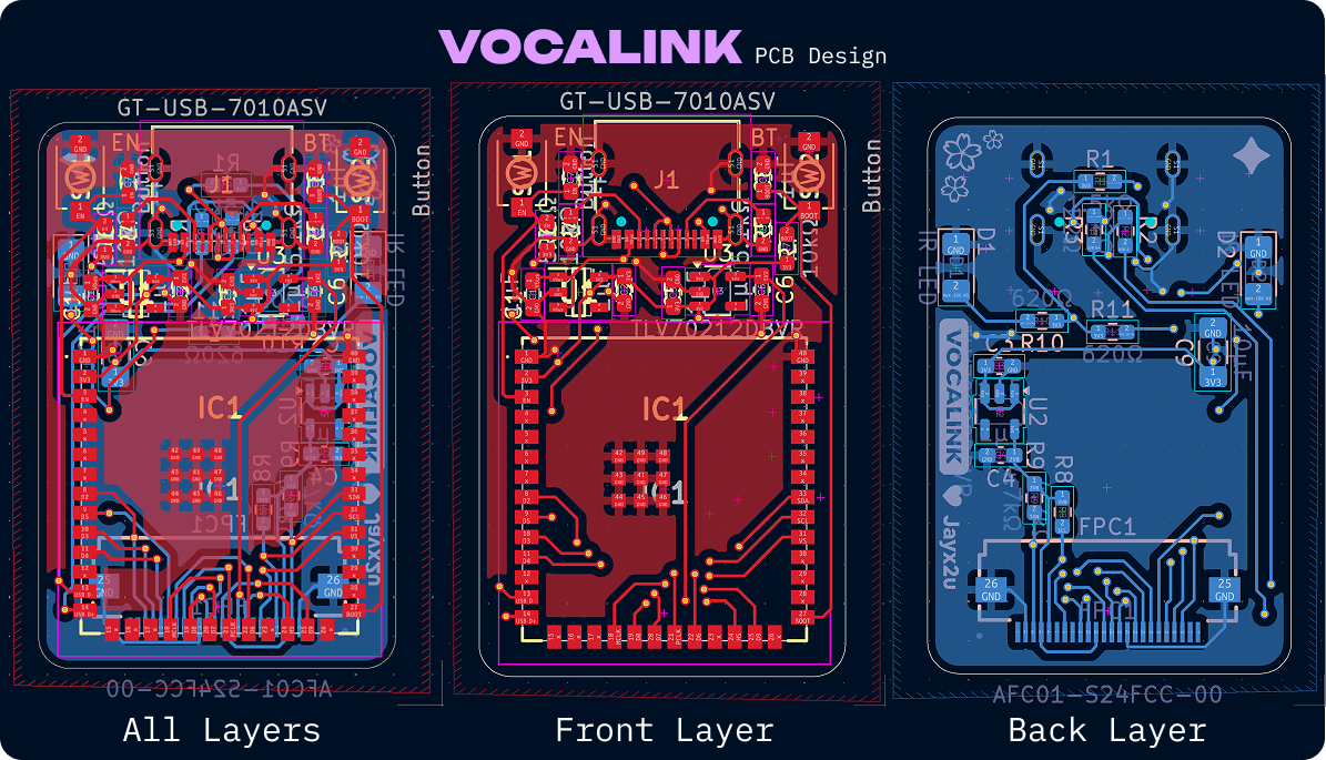
Beautiful isn't it. Brings solder fumes to my eyes 🥹. Anyways I decided to hit the sack after this.
Time Spent: 16h
2025-07-19 - Final revisions to PCB and speedrunning CAD
After a day of sleeping in down under, it is time to do the CAD. Here is a rough idea of how I want to mount it.
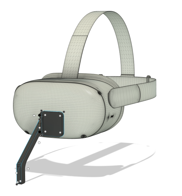
The Quest 2 model was from Nosakhae. The plan is to use some sticky film to just stick it to the front of the headset. This shouldn't be an issue since everything is lightweight. Then it hits me... how do I mount the PCB to the actual mount?? Back to the PCB drawing board:
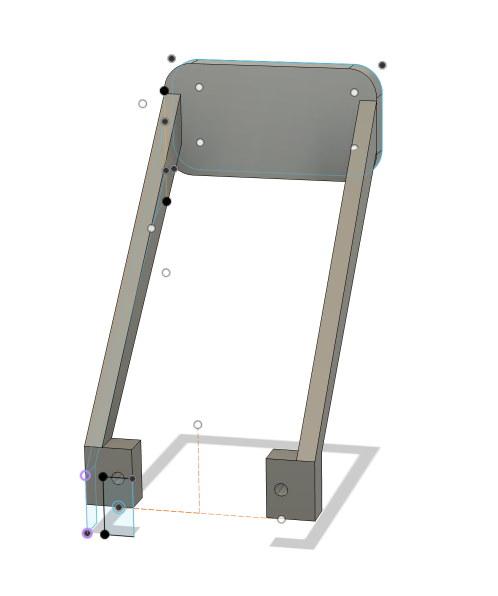
Annnnnd now it has ears. Some off camera grinding later and here we have the mount design. Looks... meh, 3D CAD designing is not my forte...
Time Spent: 1h
2025-07-19 - Beautifying the project and prepping for submission
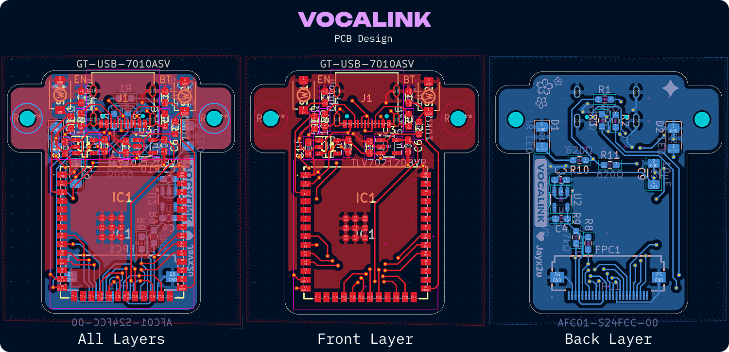
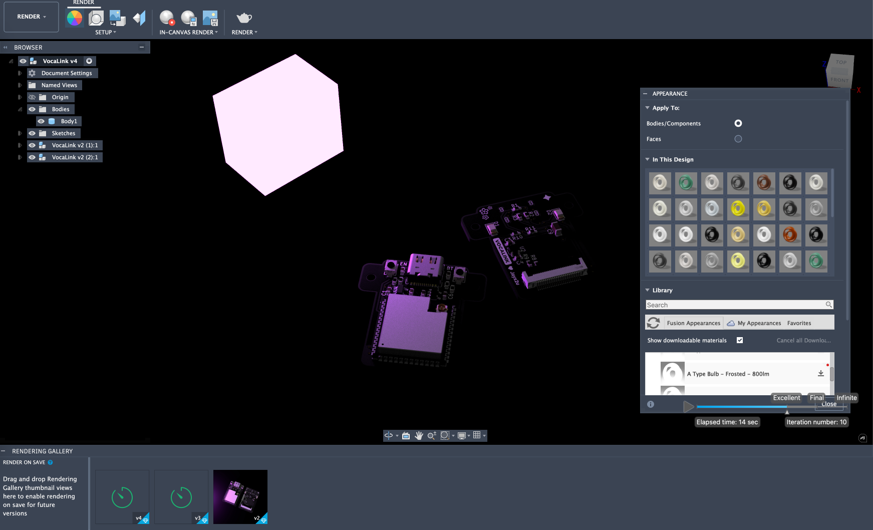
Whilst not hardware or CAD designing, I feel like beautifying a project really gives everything a finished touch. First was the renders of the PCBs. I exported the STEP files of the PCB from KiCAD, changed the materials in Fusion 360 and here is how I rendered it:
After that, it's time to use Figma to make the finals designs. You can see the end results in the README.
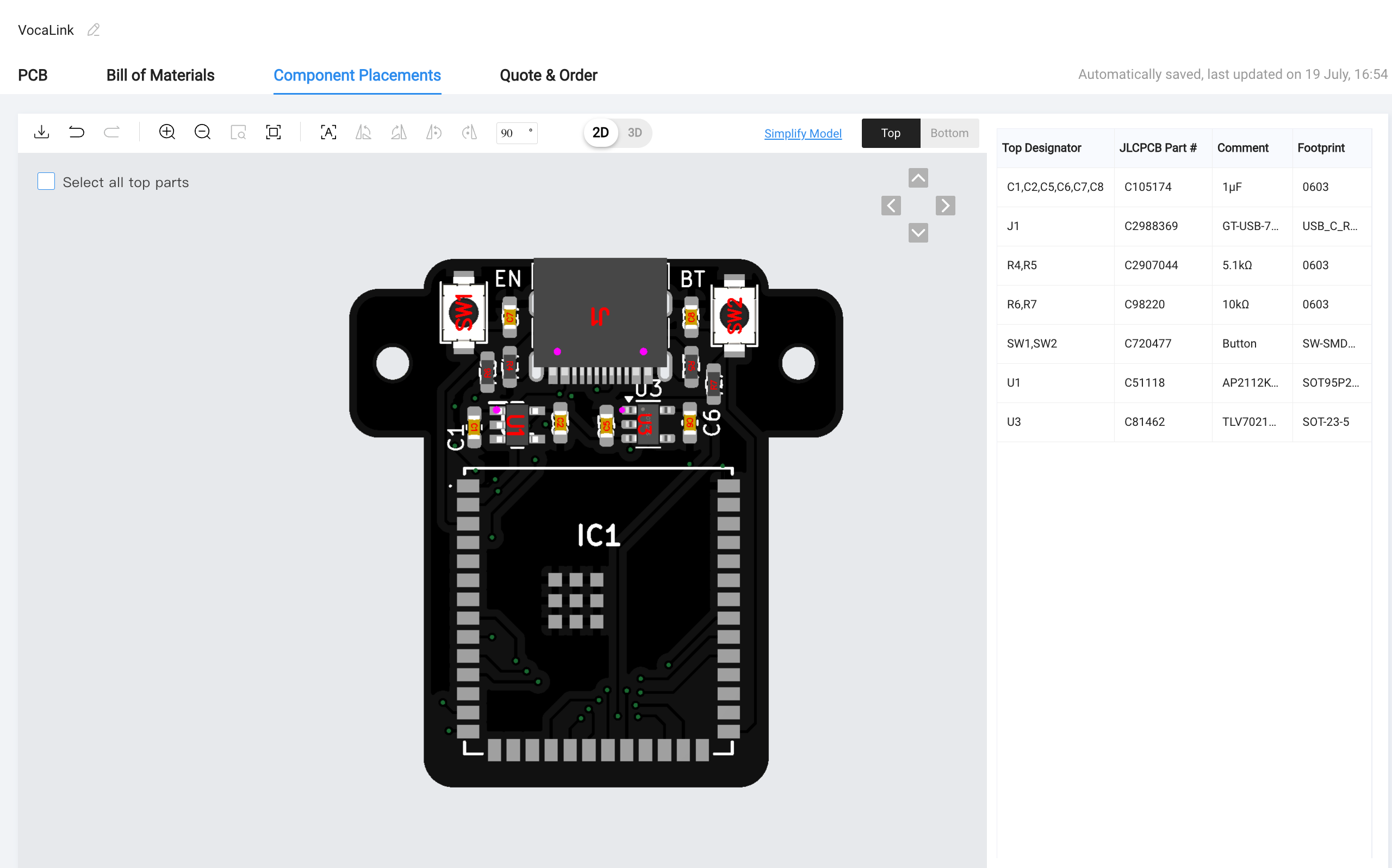
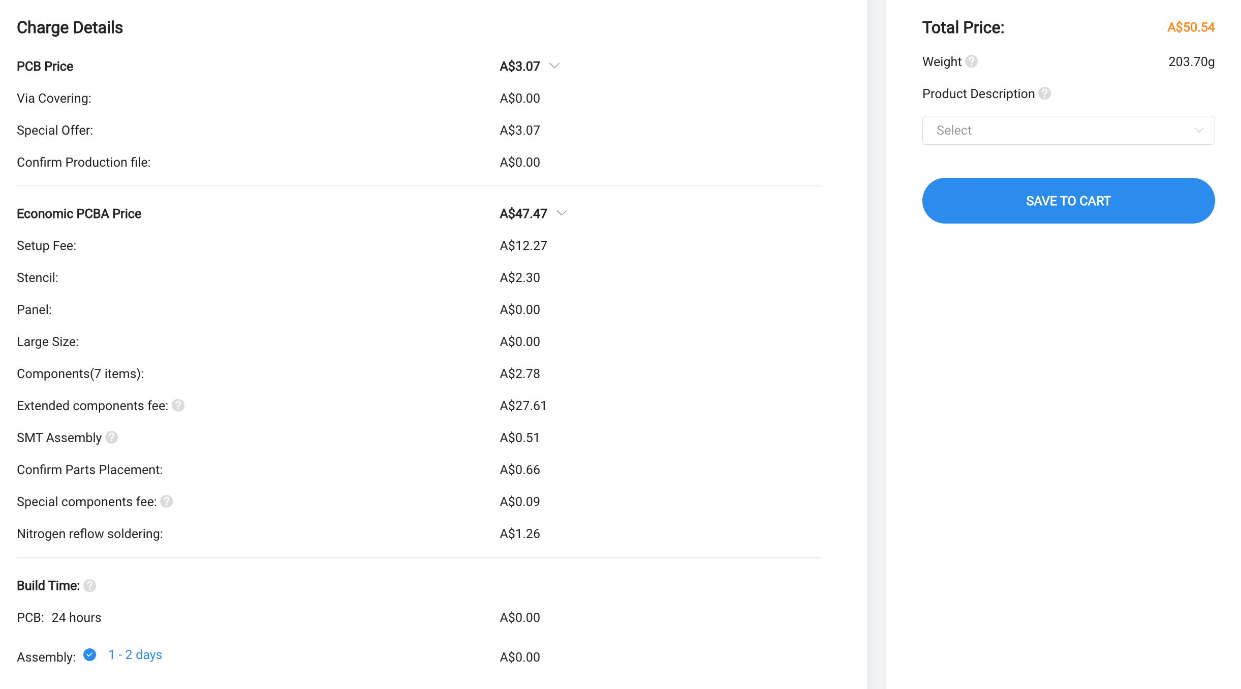
Next is BOM and production files. I made the BOM using LCSC's BOM Tool then simplified it which resulted in this BOM. For the PCBA production files, I used the Fabrication-Toolkit KiCAD library which gave me all the files I need for JLCPCB's PCBA service.
With this, I updated my BOM and the project is ready to be submitted! 🎉
Time Spent: 4h
2025-08-09 - Lock in for soldering
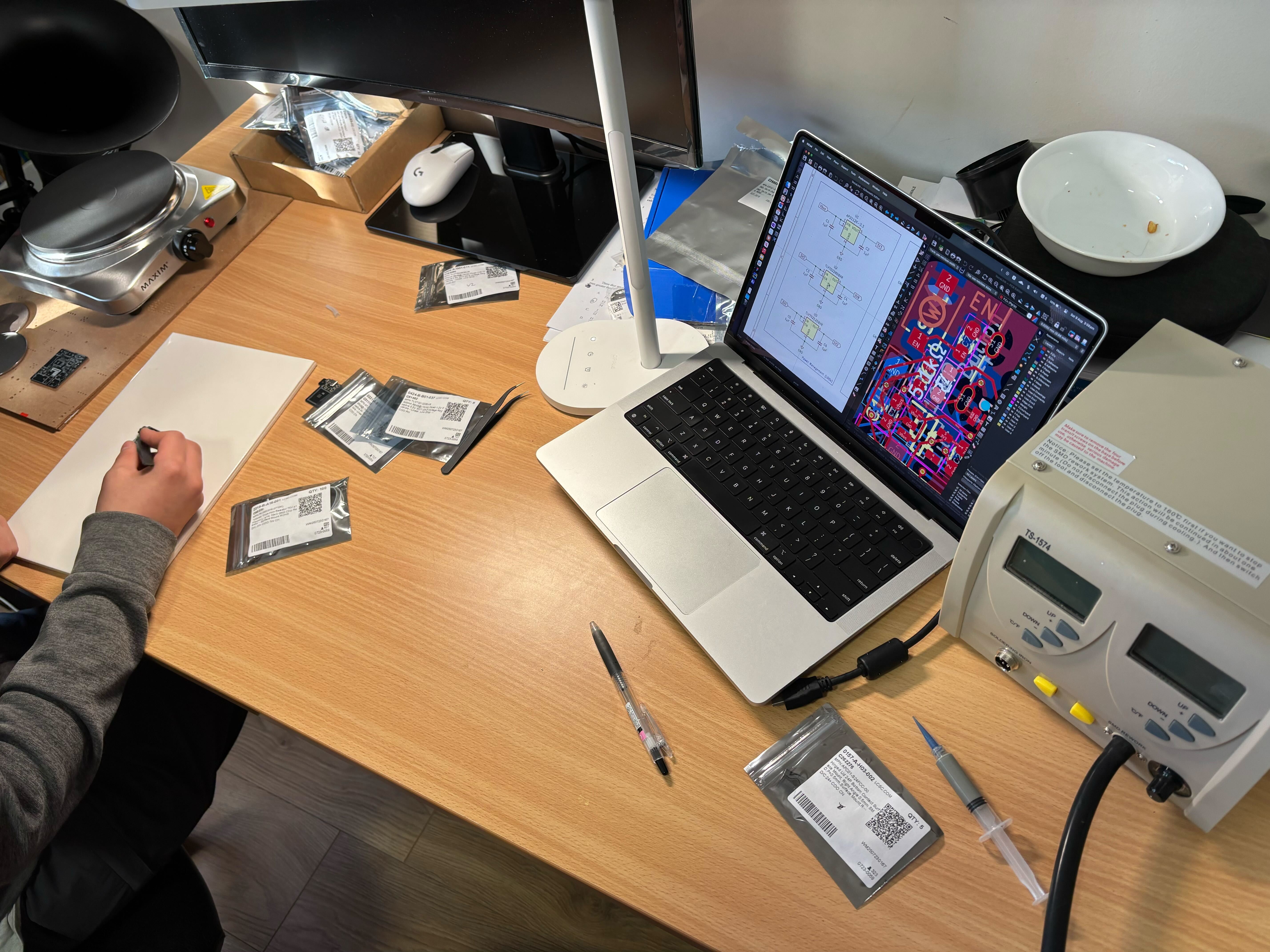
It is the day. With a hot air reflow station and a hot plate borrowed from the school, solder paste bought from a local store and a friend to help me out, it's time to solder everything...
Photo of the setup:
The soldering of the esp was fine, we just pre pasted and cooked the pcb until it melted.
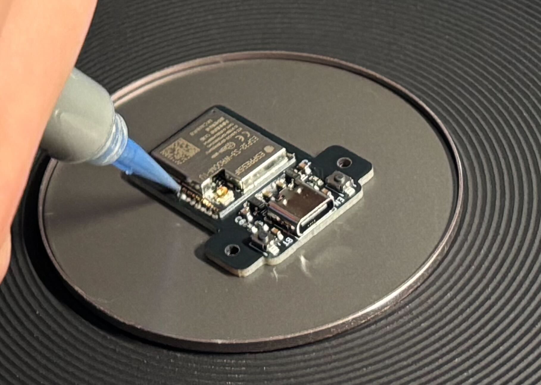
With the back of the pcb, we just pre applied the paste then held the component with tweezers and blasted hot air onto it. Worked pretty well.
All was good until we got to the FPC connector. It was so hard to solder and not get any of the pads to bridge.
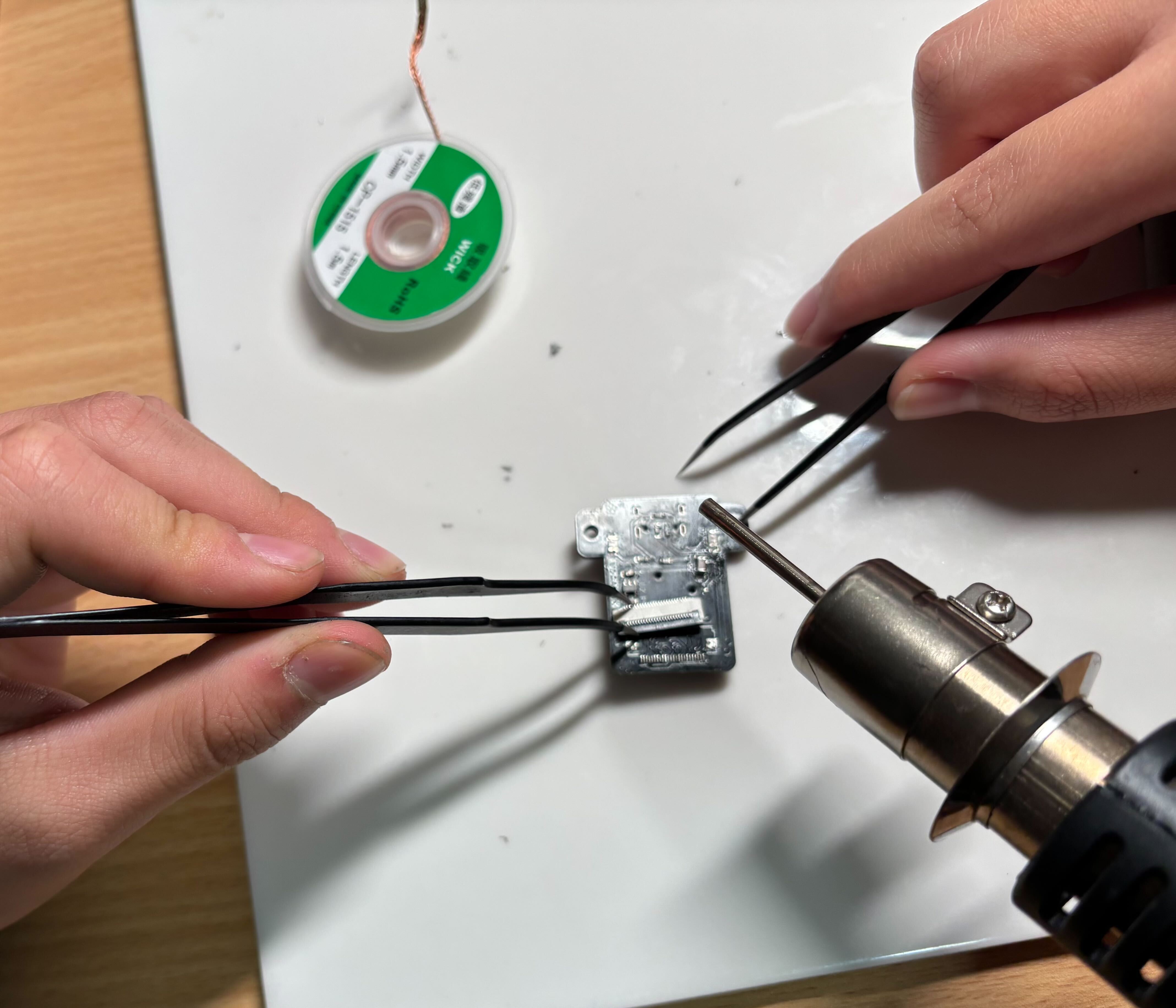
In the end... we grimaced the pads.
But all is good! We have a second pcb to attempt on. When soldering the esp on, we managed to delid it..
After that fiasco, we tried the FPC connector first, as you can see, it was prettyyyy hard
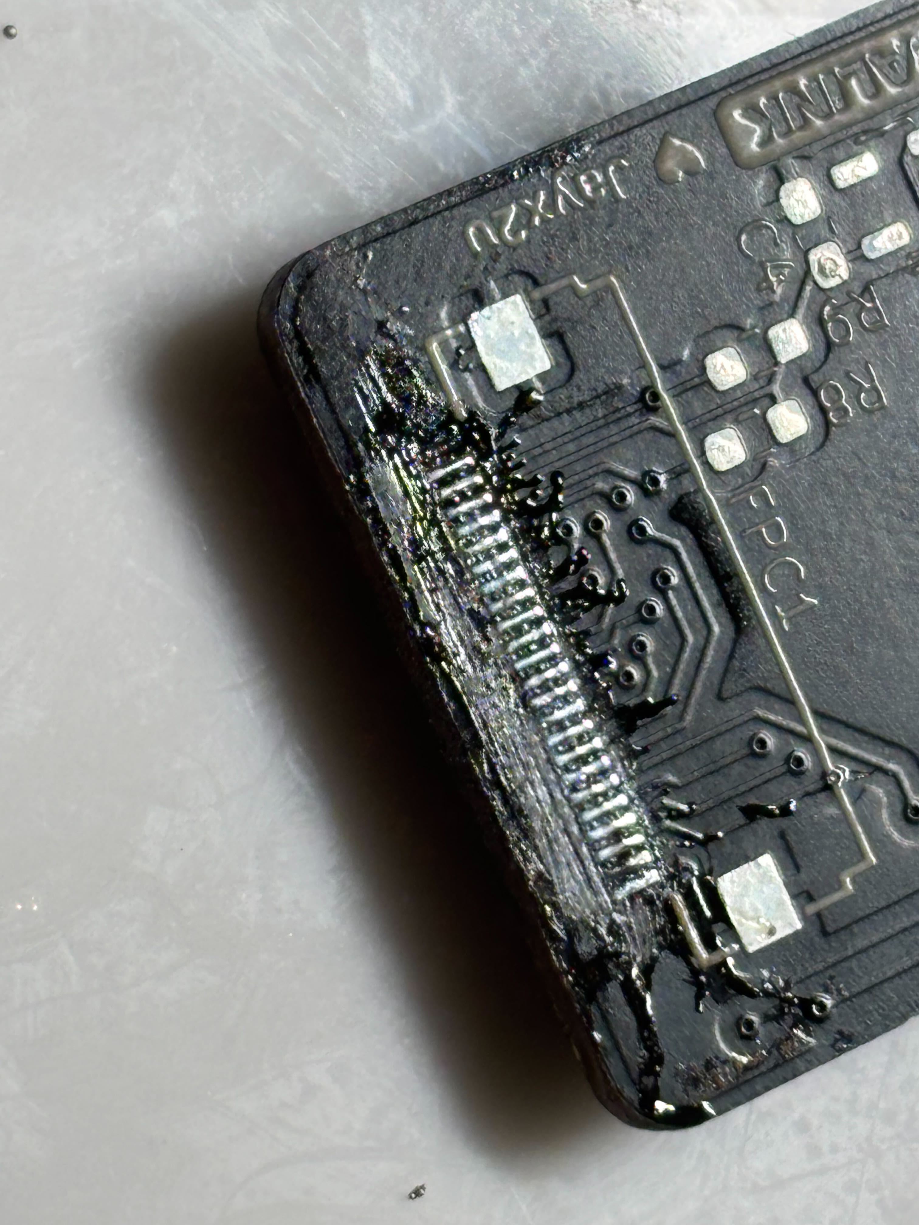
After several attempts, we got this absolute abomination
But everything seems to be fine so we soldered everything else down and started flashing it:
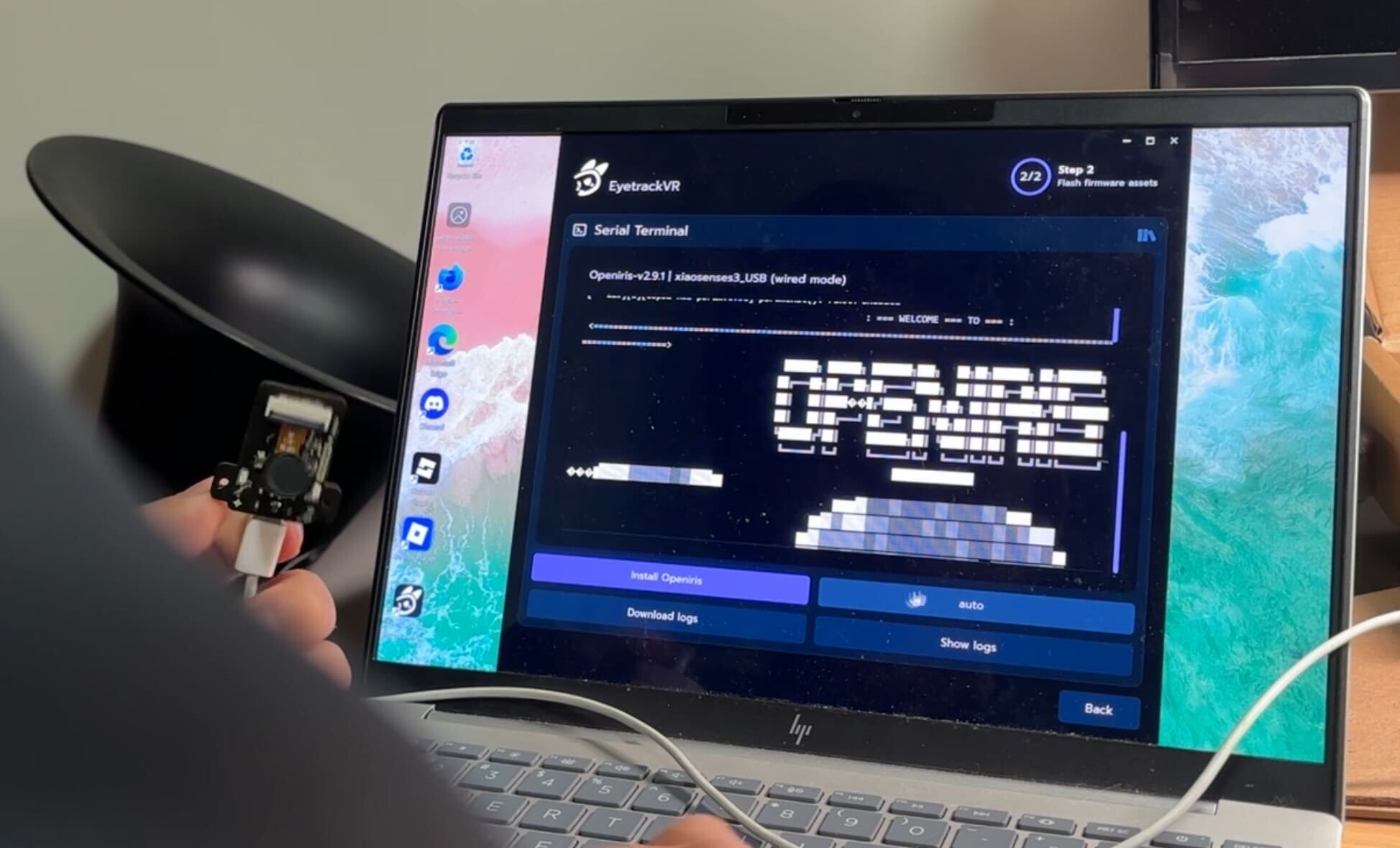
And that is the build complete! First time hot air reflow soldering... it was quite the experience
Time Spent: 8h
2025-08-14 - Finishing up and demoing
I know it is the day of the due date... we don't talk about that. I got my mount 3D printed by a friend. I attached it to my headset and this is what the finished product looks like:
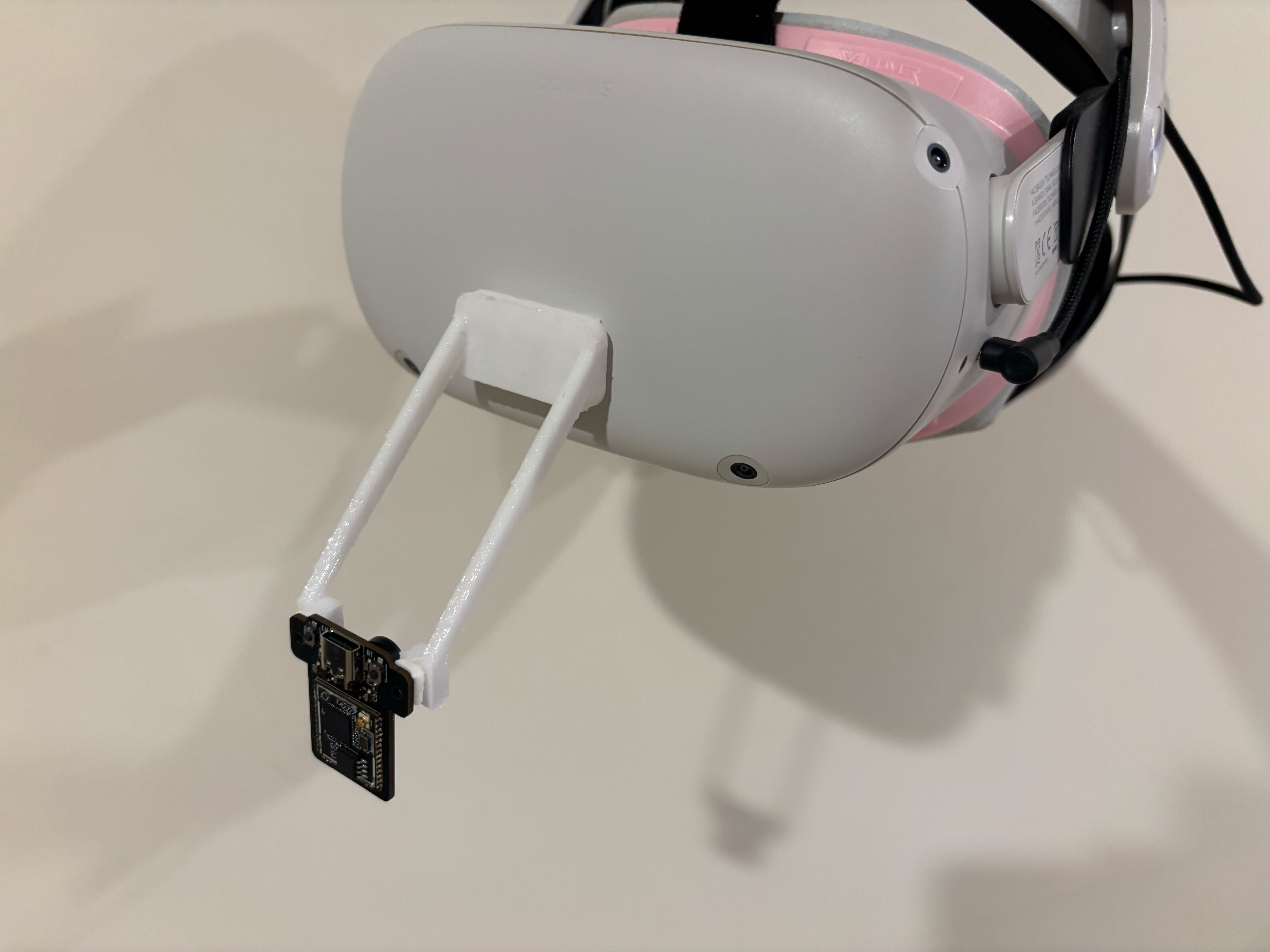
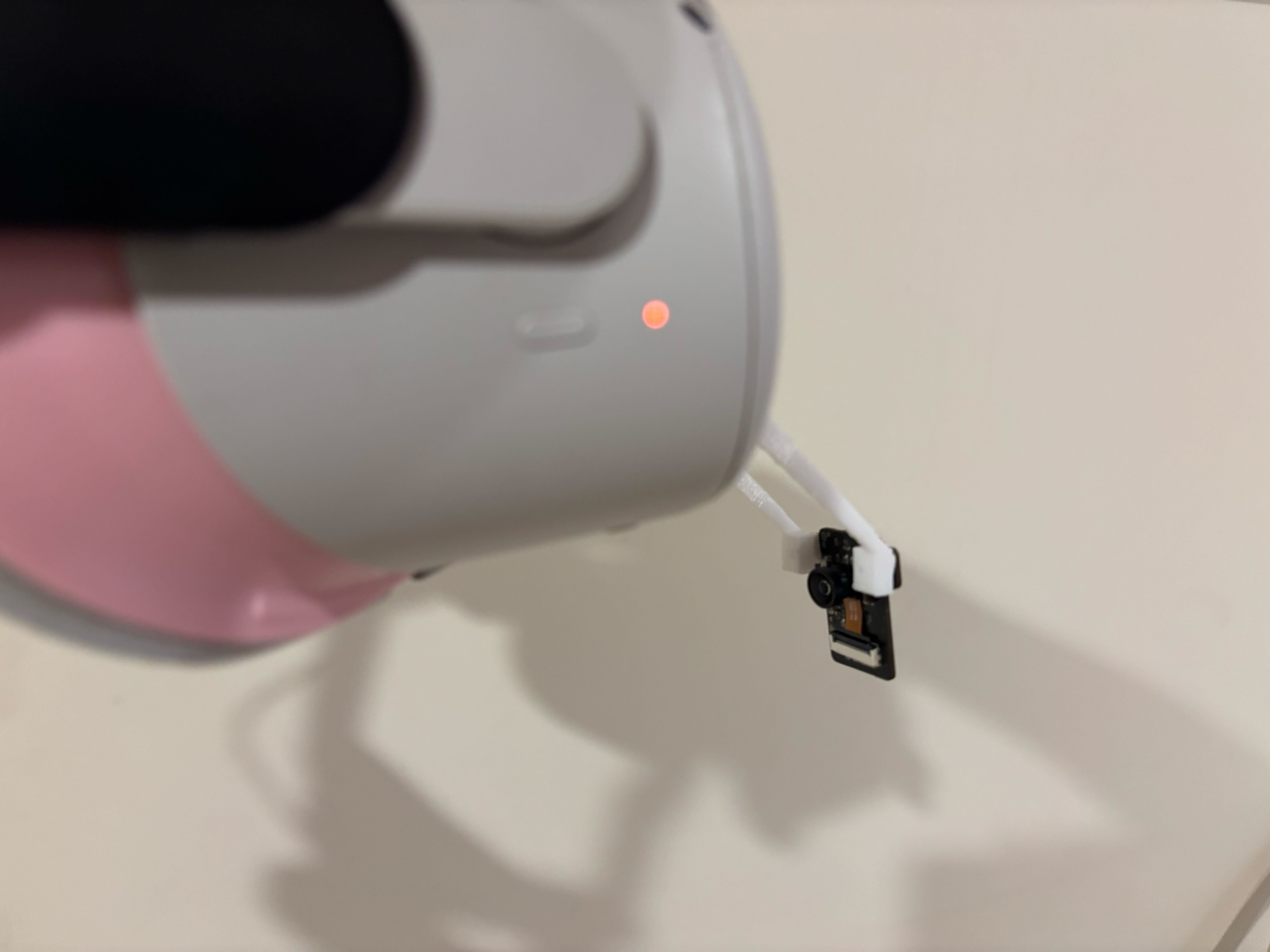
Installed Project Babble (ML model for mouth tracking) and VRCFT (software for making face tracking work in VRChat) which resulted in this demo video: https://youtu.be/pk8RPQfYxws
Time Spent: 2h