
Voice Assistant
DIY voice assistant
Total time spent: 17.5hr
I have set out to build a diy voice assistant with a 3d printed case and a high quality speaker (for its size).
Friday 16th May: Choosing a speaker driver (2 hrs)
Today I have researched different speaker drivers to choose one suitable for my project. Due to space constraints I will be using a 4or smaller driver from a reputable brand. Below I have listed some of the best options I have found below (with the LSX as being a fun
challenge" project driver).
Dayton Audio PS95
- 3.5" driver size
- 20w RMS
- 8Ω impedence
- 100Hz - 20kHz frequency response (good but lacks some of the lowest bass)
- Looks cool as hell
- Expensive at ~£40
- Circular mounting
- https://www.ebay.co.uk/itm/146374373328
Faital Pro 3FE25
- 3" driver size
- 20w RMS
- 16Ω impedence
- 100Hz - 20kHz frequency response (good but again lacks some of the lowest bass)
- Looks nice
- 4X mounting holes
- Cheap at £12
- https://www.ebay.co.uk/itm/133955301828
KEF LSX driver
- 4" driver size
- Unknown RMS
- 8Ω Impedence
- 54Hz - 28kHz (very good for its size)
- Needs crossover
- Expensive at ~£100
- Difficult to make it work well.
- Seperate tweeter and mid driver
- Useful info: https://www.reddit.com/r/diyaudio/comments/10ewn7v/comment/k7834rl/
- https://www.ebay.co.uk/itm/226630881688
Tang Band W3-315E
- 3" driver size
- 20w RMS
- 8Ω Impedence
- 100Hz - 20kHz frequency response (good but again lacks some of the lowest bass)
- High sensitivity (90db)
- Looks nice
- Circular mounting
- Good price at ~£26
- https://www.ebay.co.uk/itm/267127968217
I have chosen the Dayton driver from this list as the driver I will be using. It has an acceptable frequency response, good wattage, good impedence, easy mounting and comes second to the LSX driver on cool factor
.
Friday 16th May: Choosing an amplifier board (1 hr)
Today I have chosen an amplifier board suitable for my voice assistant. Outlined below are some options I looked at:
TDA2030A Mono Amplifier
- 7.5w at 8Ω
- Small design
- AUX input
- Volume potentiometer
- 9-20v input voltage
- 25Hz - 18kHz
- This board is not sutable due to low power and frequency range
Unnamed blue board amplifier
- 15w at 15v or 25w at 24v
- Software only volume control (Ideal)
- £1.19 (Very Cheap)
- Jumper point input and output
- https://www.aliexpress.com/item/4000124520883.html
I have not included other amplifiers in my list as many were not good enough to consider. The Unnamed blue board amplifier seems to be the best choice so i will continue designing with it in mind
Friday 16th May: Other components (2.5 hr)
Today I ran some tests to determine which single board computer would be most suitable for my project.
I ran my test on a PI4, Pi5 and Pi0. I installed raspian and connected a USB microphone then ran whisper real time speech recognition (a custom stack) on each device to determine which one was most sutable for my task. The Pi0 came out last being too slow and taking up to 20s to process speech. The pi4 and 5 were both fast with the pi5 having an edge of about 1.5-3 seconds. Due to needing fast speeds in order to keep the project feeling smooth, I will be using a PI5.
I am also going to use an LED strip to show the status of the device. The LED strip will be placed at the top in a ring around the devices circumference. I have chosen a WS2812 LED strip due to its 5v input level.
I have also chosen other various electronics and made an initial BOM.
Saturday 17th May: 3D modeling (3 hr)
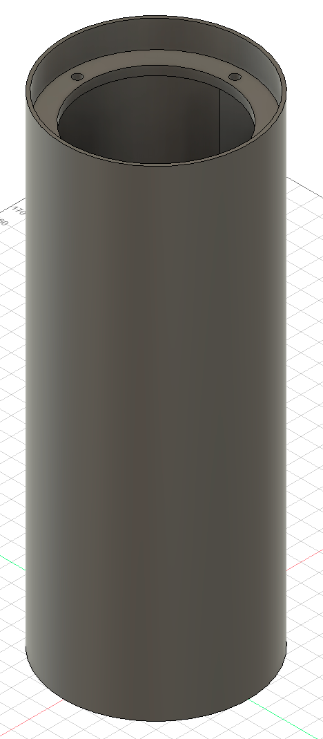
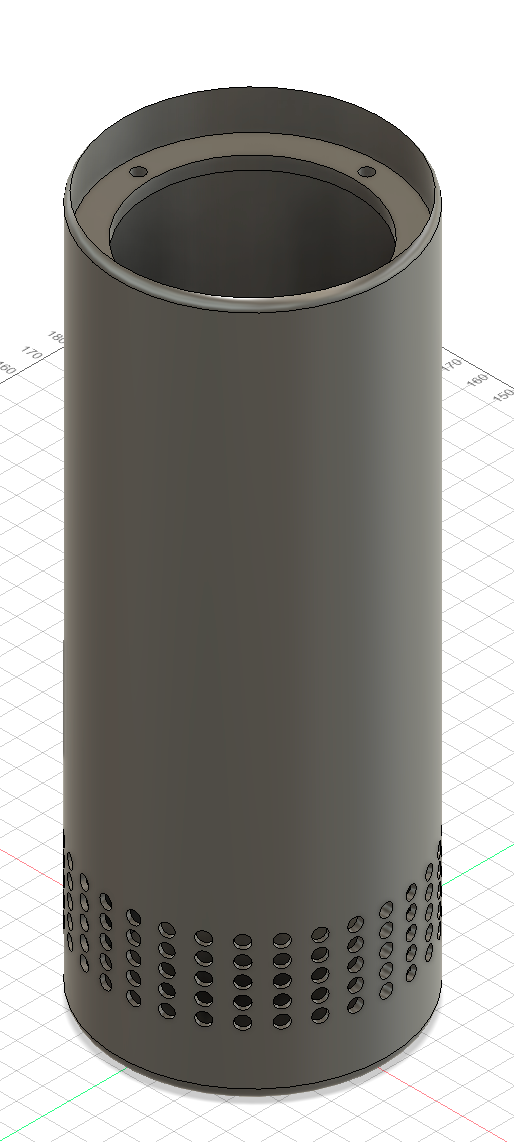
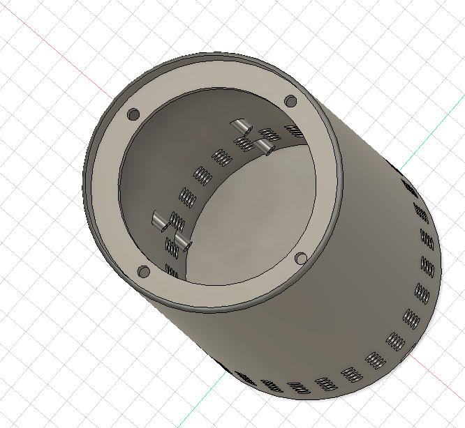
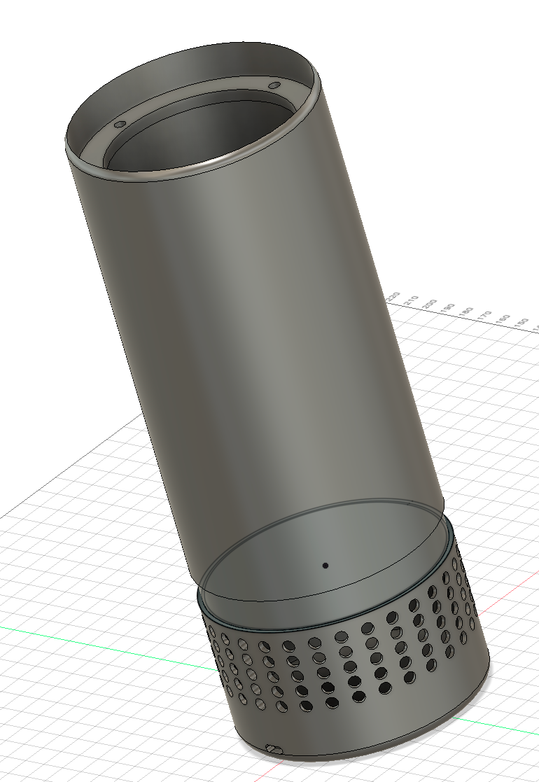
Today I begun to 3D model the casing for my design. I first reasearched the specifications and mounting dimension for the speaker. The speaker benifits from an open back design with the long casing acting as a bass reflex tube to give a better bass extension. I then added a series of holes to the bass. There are 45 rows fo 60 holes (300 total). These primarily allow sound to enter the casing to allow the microphones to pick up an input from the surroundings. They also allow the sound from the speaker to travel out the bottom of the speaker to aid the bass reflex design. They also allow the casing to stay cool by allowing air flow to the Raspberry Pi fan. From beginning to research schematics and optimal designs for speaker mounting to concluding on this shape, design and dimensions, I spent 3 hours.
Saturday 17th May: 3D modeling (5 hr)
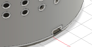
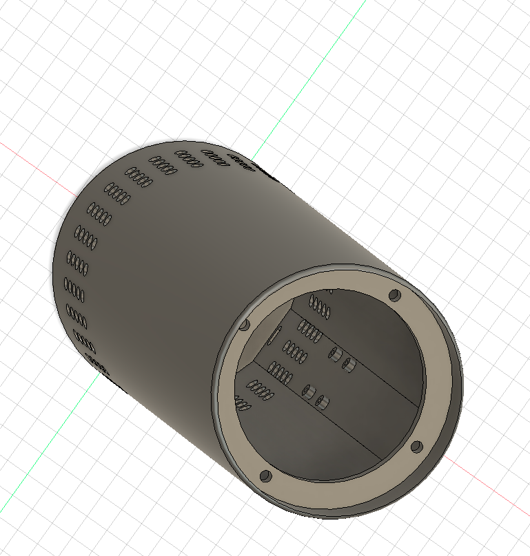
I spent a second set of 4 hours adding mounting holes for the electronics. I started by researching mounting dimensions for each part then adding a USB-C port to the bass for power input. This allows the unit to be powered with a suitable USB-C PD brick. I then found a specification for my amplifier board and added suitable mounting holes. Next I added mounting holes for the Rasperry Pi. I chose to side mount the raspberry pi to keep the base diameter as small as reasonably possible. By side mounting the electronics, the unit also has better heat dissipation. Next I added a ring for the LED strip. This ring is 14mm trall to allow the led strip to fit and has a slot on the back side allowing wires to be pulled through. This LED strip will have a diffuser placed over it to allow for better light diffusion. The internal lip that has been created is smooth to allow for easier printing.
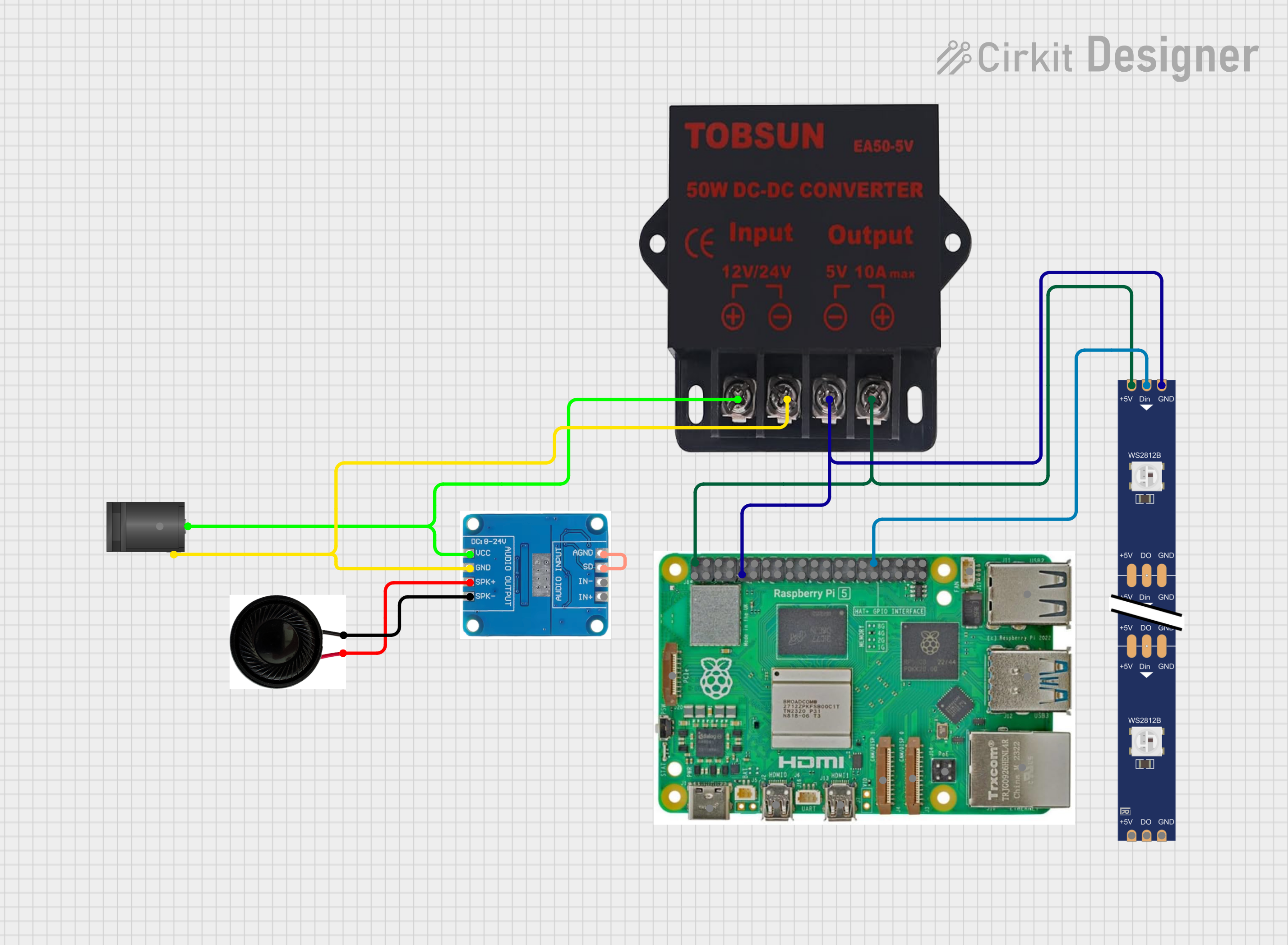
Sunday 18th May: 3D modeling, Revised BOM, Circuit Diagram (3 hr)
Today I began to design a circuit diagram instructing how each part should be connected. While designing this diagram, I realised my USB-C power delivery board cannot sufficiently power the electronics in my device, this is because the electronics are exteremly power hungry meaning a very high power USBc brick would be needed. I have instead opted to use an external 12v brick (to match the amplifier voltage). I will then use an internal buck converter and a regulator to supply 5v for the Raspberry Pi and the LED strip. I have chosen a high current power brick to ensure there is enough current for all electronics. I have found suitable parts and updated my BOM to reflect the changes.
I then removed the USB-C port from my model and replaced it with a barrel jack to take input from my 12v power supply.
The barrel jack input powers the amplifier and the buck converter. The buck converter then powers the LED strip and the Raspberry Pi. GPIO pin 12 is used for the led strip as it is exposed by the audio HAT. The audio output from the hat will be used as an input on the amplifier board.
Sunday 18th May: ReadMe (1 hr)
Wrote a readme, see