
Homeassistant automatic greeenhouse
Automatic greenhouse with Homeassistant integration.
Journal
Here you can see a documentation of the entire development process.
Total hours spent: 80h
May 25th (30m): initial setup
Just setting up the Git Repo. Finding some cool badges for the README.md file. Doing some parst reasearch.
![]()
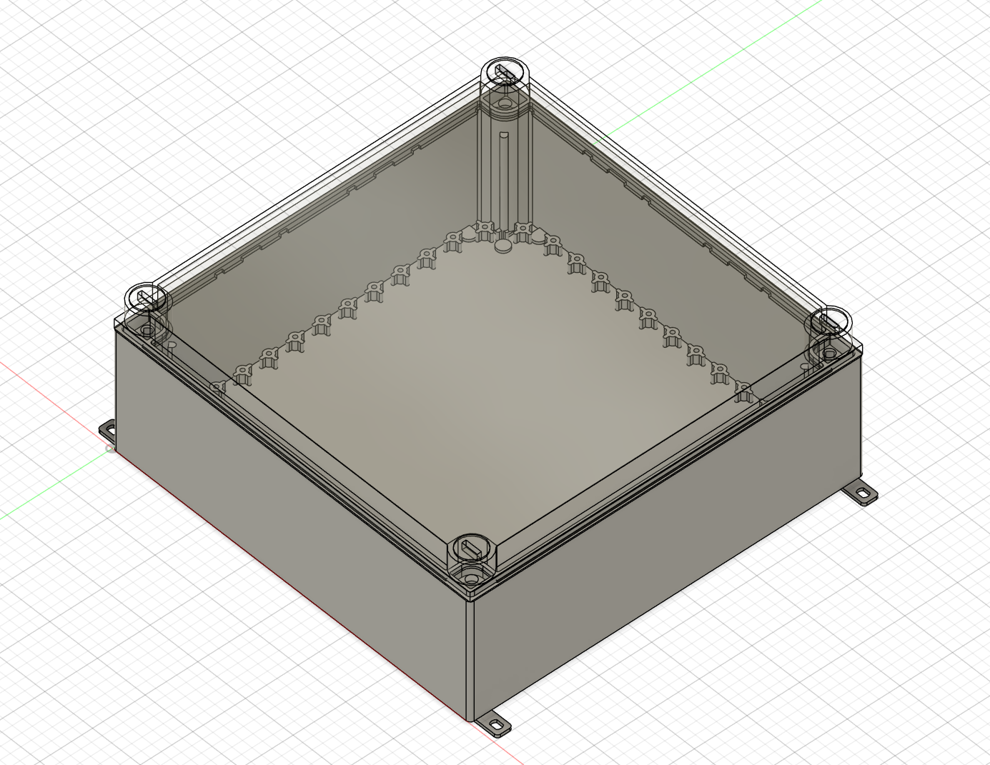
May 29th (1h): start desingning core electrical box
Finding 3D Models for electrical box and other parts. It actually took some time to find a 3D model of the electrical Box I want to repurpose for the project. And because I am sometimes a lazy person [here its more about effectiveness; who needs to design a box when manufacturues profide the files :)] But from my experiente they like to hide them.
I eventually found the .stp files I was searching for and imported them into Fusion 360. Looks great and will defenitly better visualize the Idea and is perfect for planning.
May 30th (7h 30m): configuring my electrical box
Session 1 (1h 30m)
I just wrote some imortant stuff to the README and build a logical project structure. The README also explains the concept of sensor modules. The concept of sensor moduels I introduced makes it easy to adapt and adjust the project to you individual needs. I added a License fole just to be clear on how the project can be used in the future.
Session 2 (2h 30m)
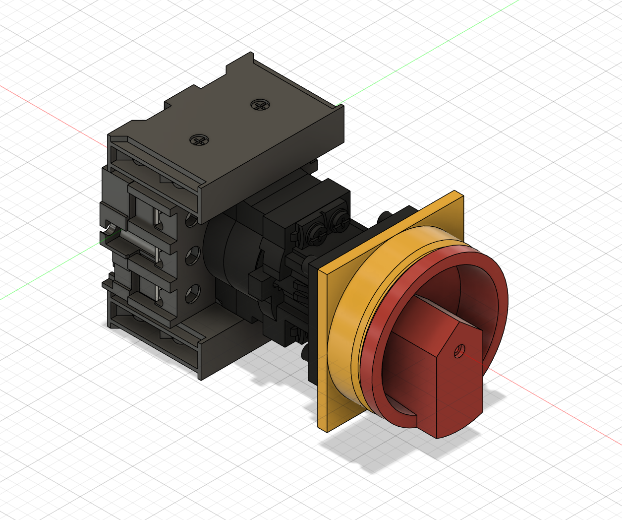
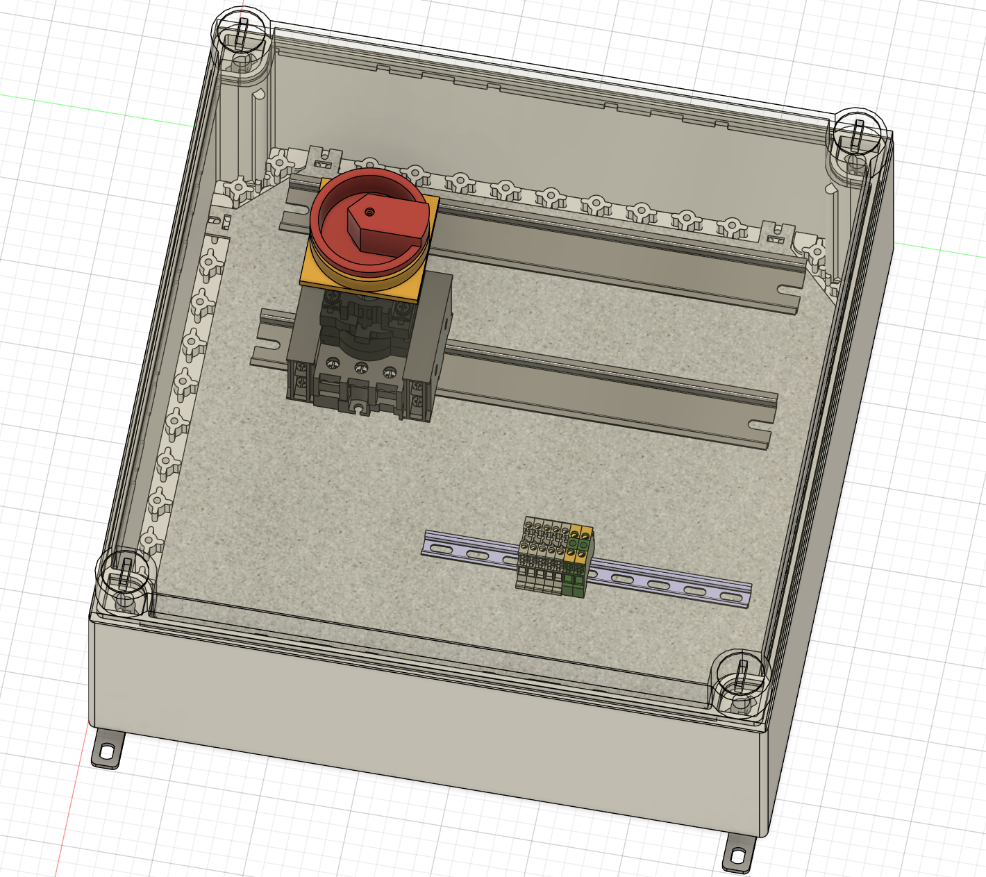
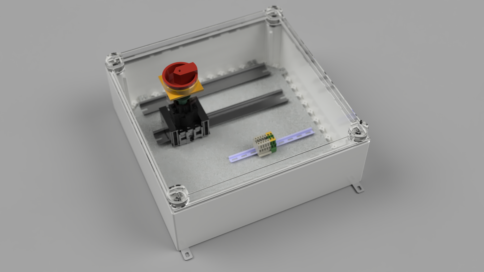
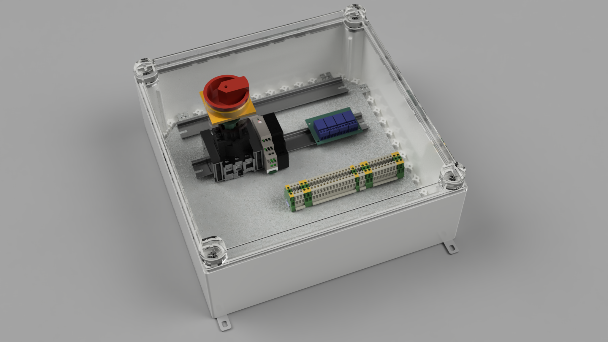
I modeled some parts on my own like the ground plate on the inside of the box where everything is mounted. Furthermore I added the main switch and DIN Rais inside the box with some terminals for the wires. I also decided on writing sub README files for the individual folders bacause Github can't display lager 3D files. Now there will be great renders right in every directory.
Session 3 (2h 30m)
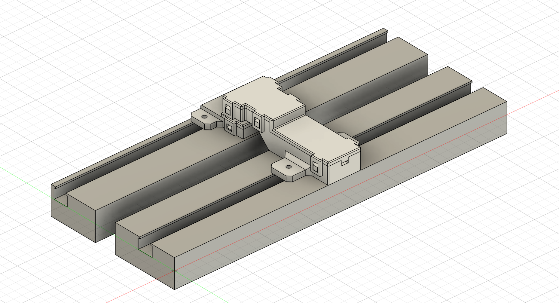
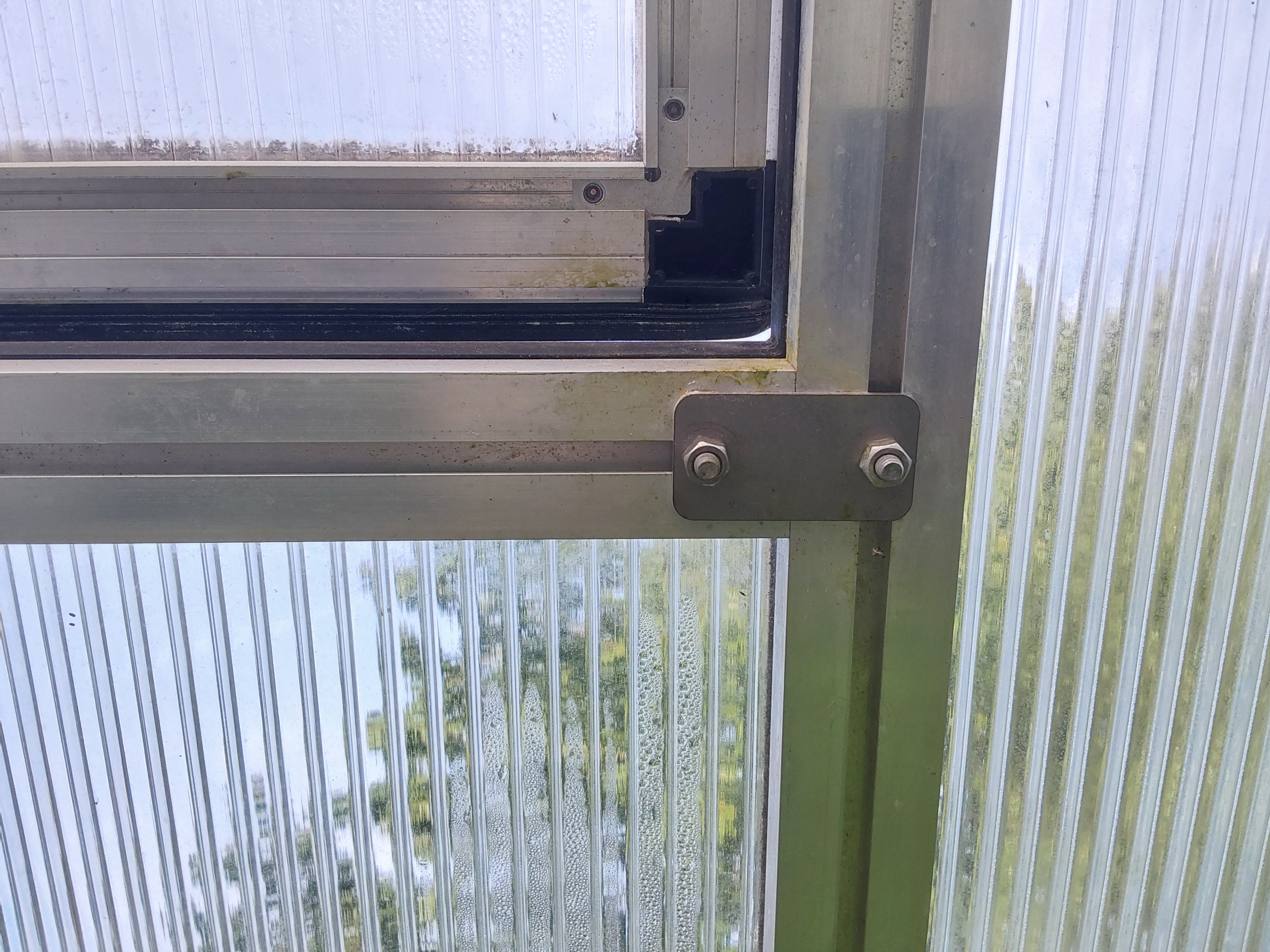
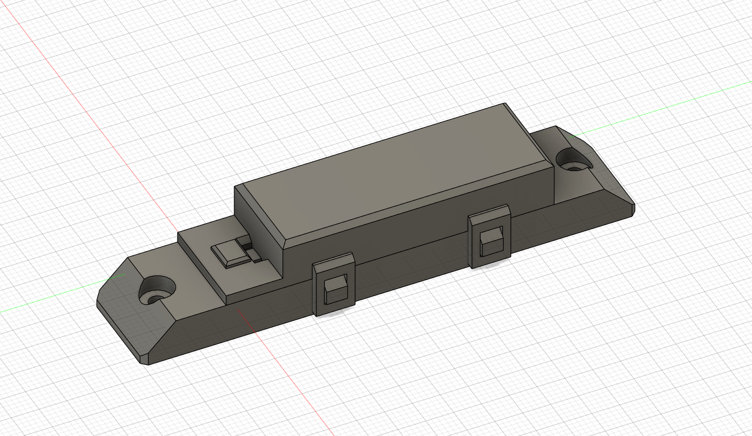
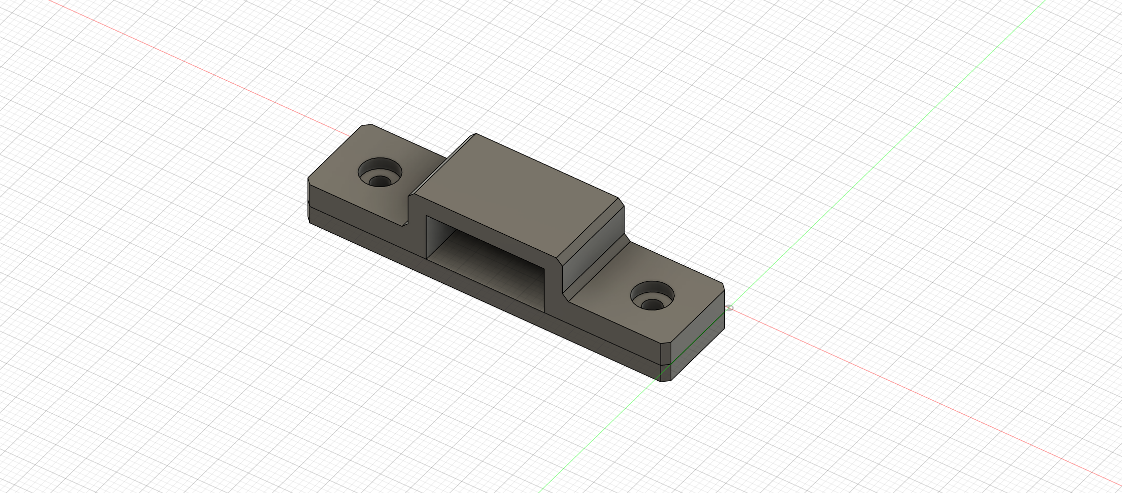
For the first sensor modul to design I decieded on the window contacts which are based on reed switches and magnets. These sensors will be designed for our greenhouse and the aluminium extrusions it uses. To attatch my 3D printed parts to the aluminium extrusions I thought of M3 screws and corresponding nuts. The case fo the reed sensor and magnet are designed in such a way that ti is possible to assemble the housing without screws just with the clips on the sides.
Session 4 (1h)
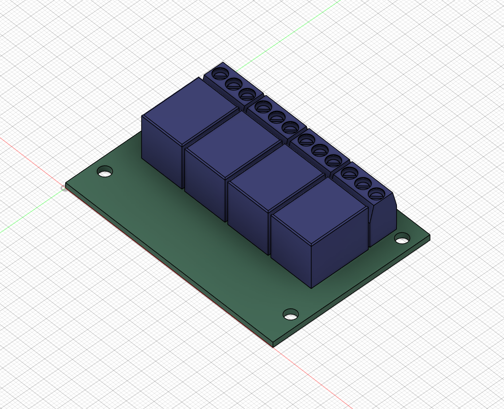
I am going to desing cases for all components so they can be mounted on the existing DIN rails. But to build a case around my parts I first need them to be in CAD. Because my relais module is out of production and the screwholes are custom for almost every board out there I quicly sketched up mine. Besides I modeled the bottom terminal row completly like it is right now in real life. Additionally I added a 5V and 9V rail mounted powersupply. The 5V one is for the ESP and relais board while the 9V one is for supplying the solanoids with power. The solanoids will be controlled by the relais board.
June 5th (2h): add some branding and Dallas sensor module
Session 1 (1h 30m) during live call
I thought my project could need some proper branding and logo to let the README look nice. As my go to software for vectorgraphics I used Inkscape to do the logo. As my Project is compatible with Home Assistant I started with importing the Homeassistant logo. For my logo I wanted something that is simple and matches the astetic of Home Assistant.
![]()
![]()
![]()
Session 2 (30m) during live call
I have added the Dallas temperature sensor module. Mostly it was code because the ground temperature sensors are already encapsulated. In my project two of those sensors will be used just for fun and because I have them laying arround. It defenitely will be interesting to see how the ground temperature is changing over the day.
June 23rd (6h): desinging sensor modules
Session 1 (2h)
After creating a cool loking logo and branding I decided to go on with designening the sensor and action modules. The next one in line was the light sensor module. Measuring light intensity might be really interesting to see in a greenhouse environment.
I also decided on using a new standardised format for each sensor and action module. Each of them has it's own Readme with a seperate BOM this should improve the experience for users who want to build a simialr project but don't need as many sensors.
Session 2 (1h)
I have updated some sensor moduel READMEs now to accomidate the new format. Additionally I finished the homeassistant configuration for the window and door contacts. Some inforamtions form the window contacts module regarding 3D printing instructions was also copied.
Up until now I think the README for the window contacts is my favourit with its animated gif ot the CAD model and the BOM with parts at the top.
small break
visiting the greenhouse and touching some grass outside :) aka not beeing glued to my monitor
Session 3 (1h)
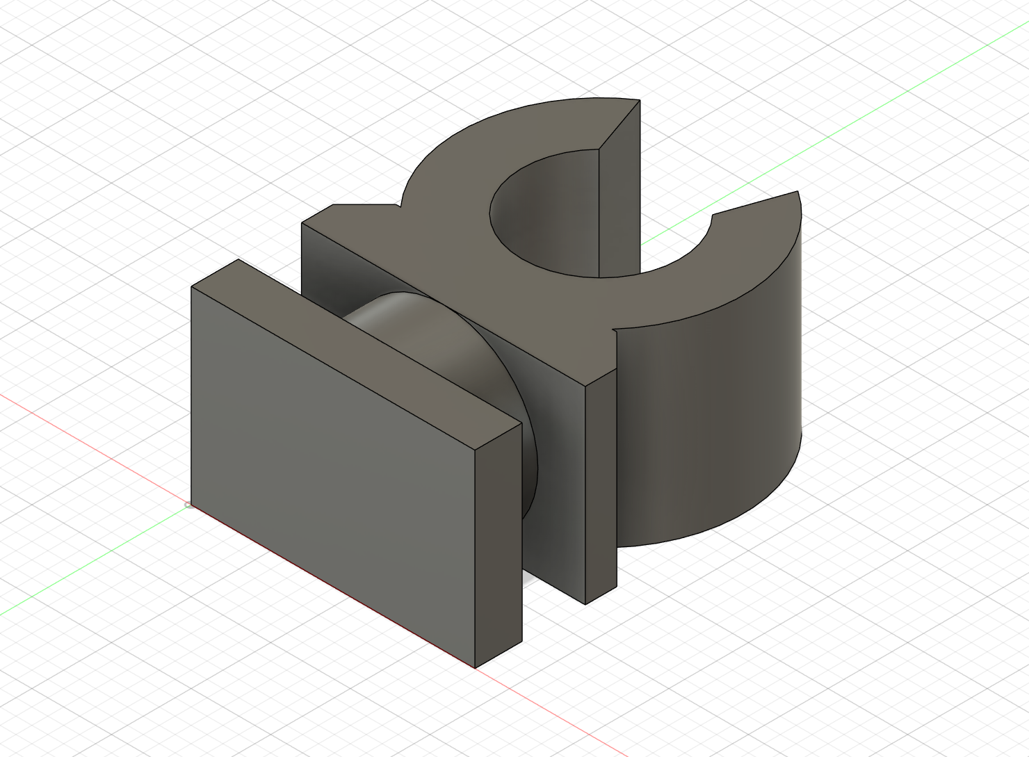
New sensor module! I have most of the parst already at home so Hackclub doesn't need to pay for them. One sensor that will be particularly interesting for greenhouse monitoring is a CO2 sensor which I unfortunately don't have. So now it's the time to add it to the project. It is is bit more expensive thatn a DHT22 or other sensor but with about 20$ also won't break the bank. Designing a mounting system was a bit difficult because I had nothign to measure of but I eventually found a datasheet with dimensions on it. In the end I decided to design a simple clamp over the sensor that can be mounted to the aluminium extrusions with two M3 screws and fitting nuts.
Session 4 (1h)
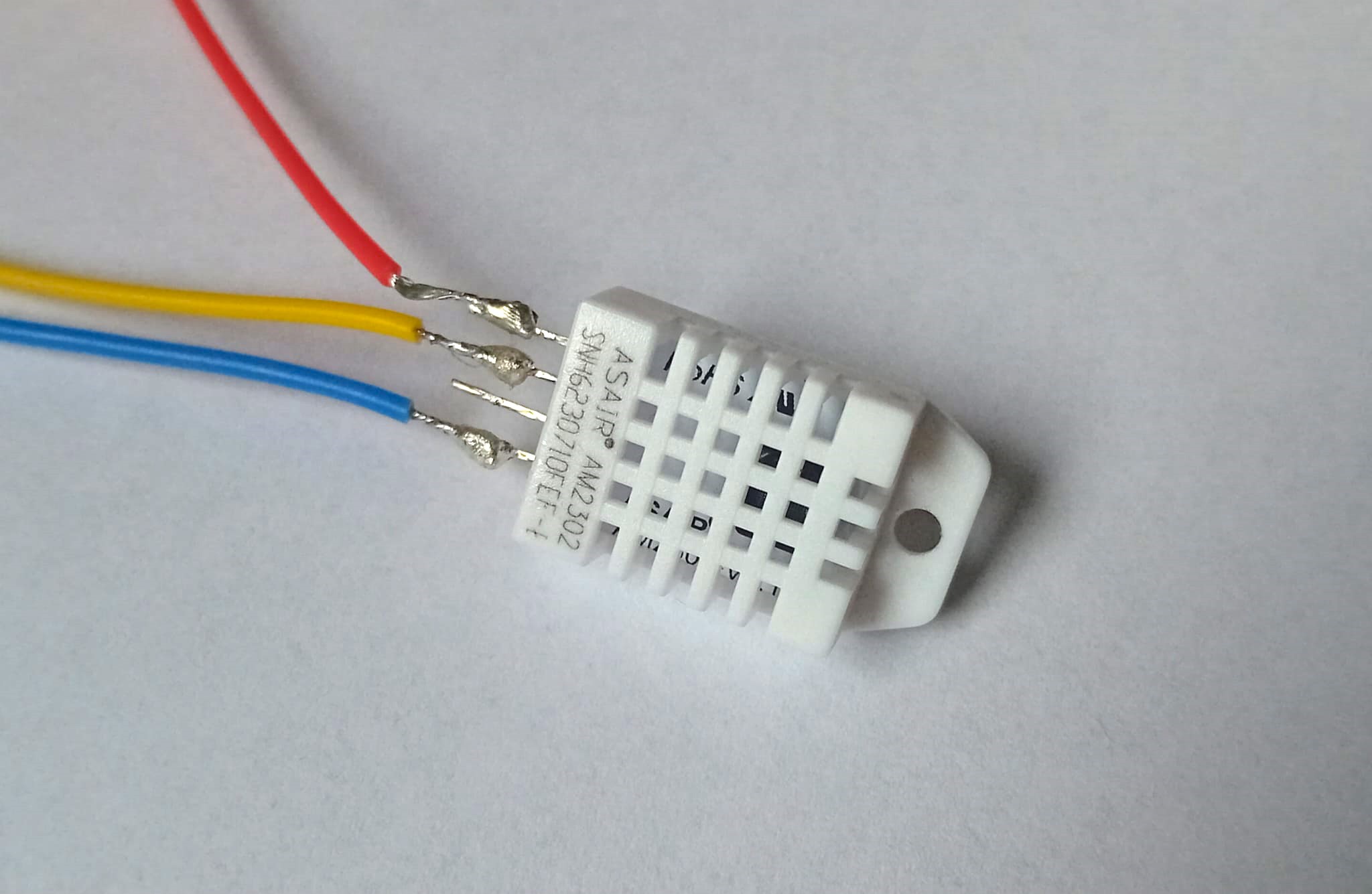
One of the last sensor modules. Yeah! I have soldered some wires on the DHT22 sensor I had in my drawer. Forunately The sensor as a 3mm hole at the top so a M3 screw fits perfectly and I don't need to desing a custom mounting solution. I thought about adding a 3D printed shield for the sensor to protect it against direct sunlight. Currentyl it will be mounted behind the aluminium extrusion of the greenhouse so direct sunlight hopefully won't be an issue.
Session 5 (1h)
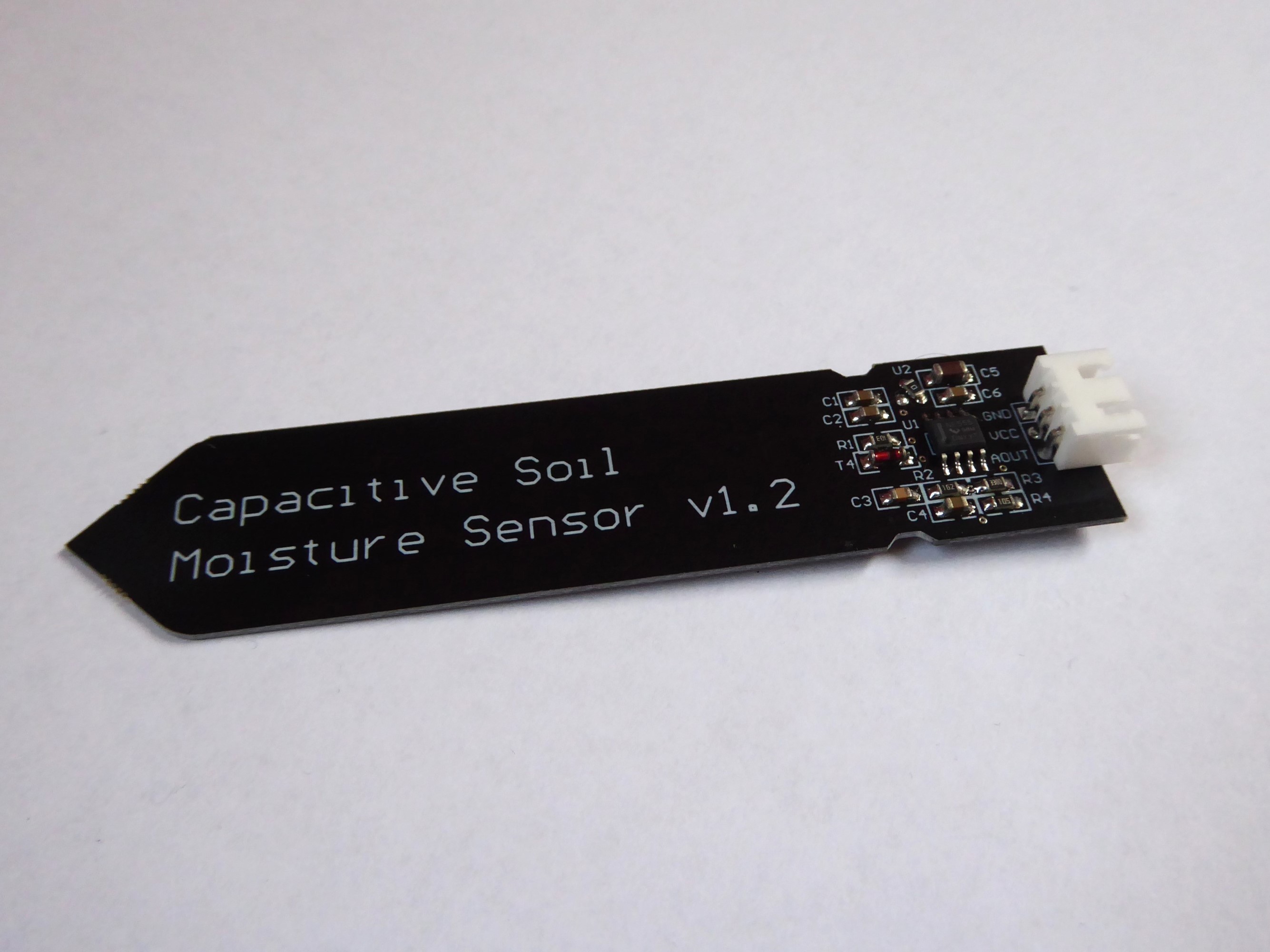
For now the last sensor module is complete. Prpbably the most important one for a greenhouse automation, the soil moisture sensors. i decided to go with capaciative ones pecause they dont degrade or not as easealy as some others with metal rods. Additionally I had themy lying around so why not use them :). The Homeassistant configuration I build also contains the calibration logic that has to be used once to tell the sensor what is dry and what is wet. Somebody rebuilding my procet can therefore easily build a similar setup.
June 24th (13h): Setting up Homeassistant
Session 1 (3h)
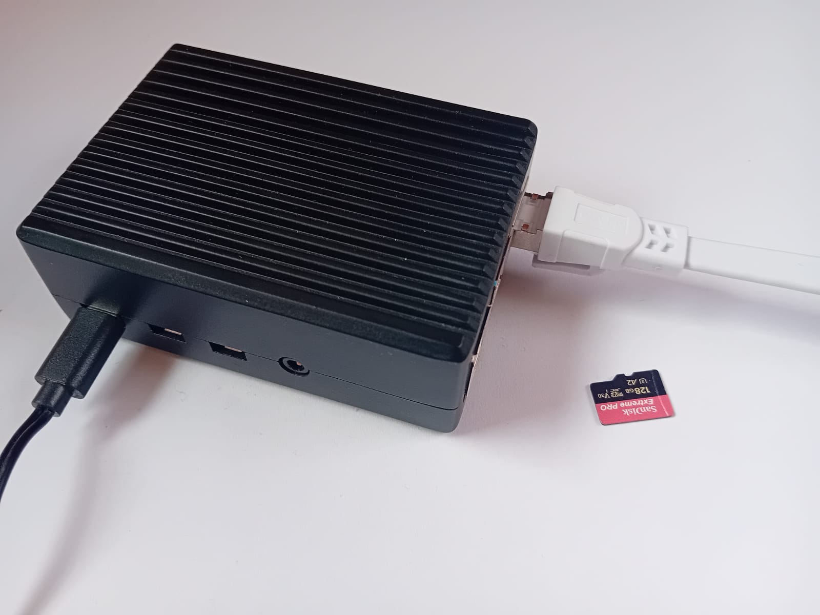
I grabed my Raspberry Pi 4 B and an SD card and got right to installing Homeassistant for testing. In the future I will be running Homeassistant inside a VM on my NAS which is running TrueNAS Scale. While the image was downloading and later on installing on the Pi 4 I put togetehr a first prototybe with all the sensors I already have. I am going to use an ESP32 with ESPHome on it.
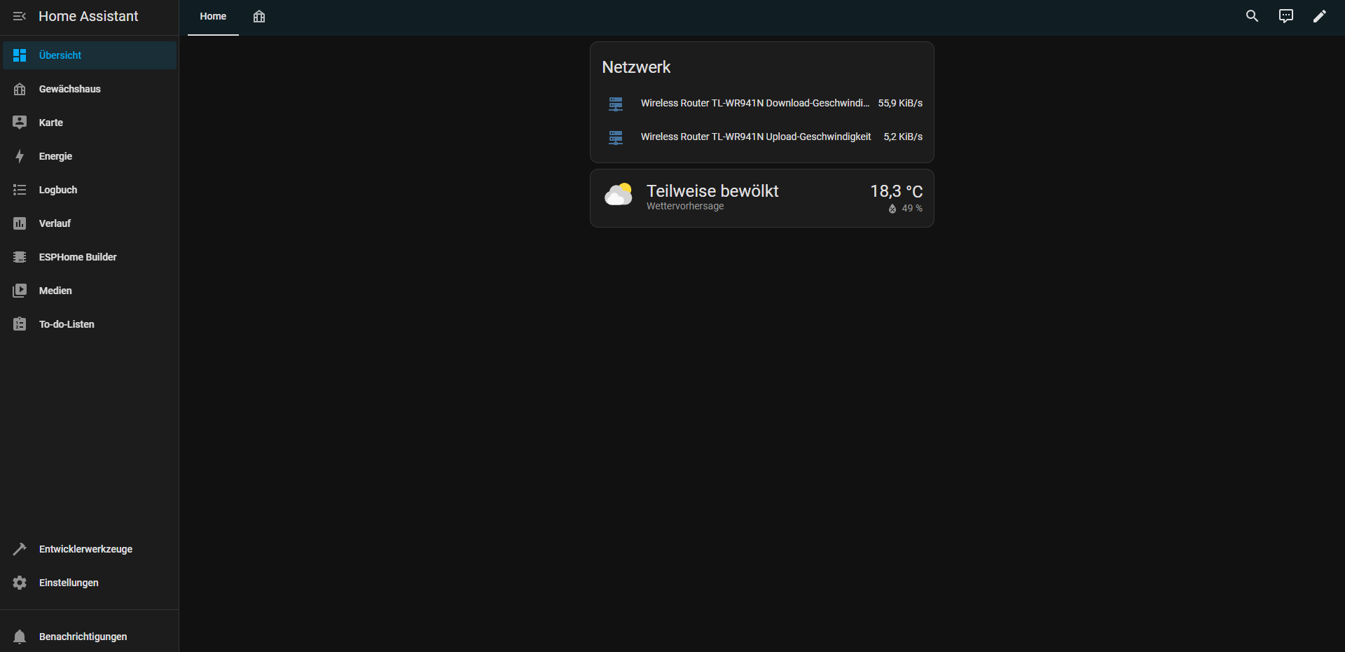
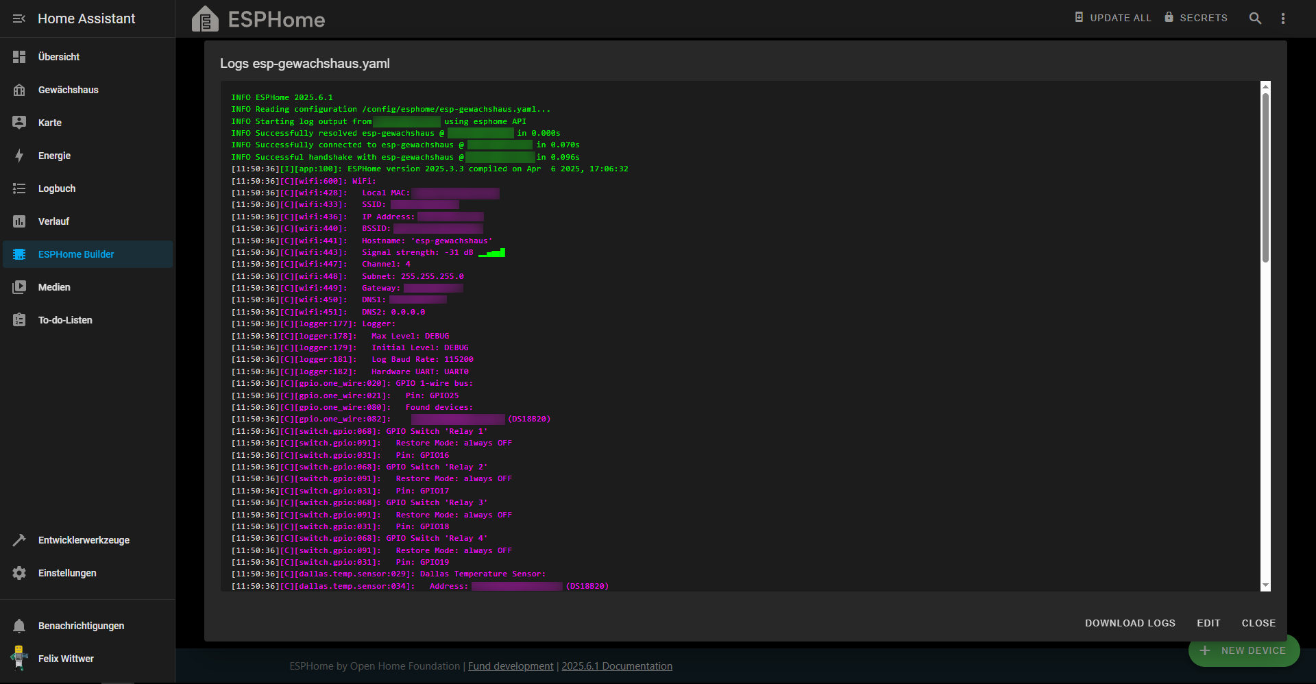
I directly connected the RPi4 to our Router via internet and noticed that it is actually supported by Homeassistant automaticaly and I can now monitor aour nethwork useage via Homeassistant, cool stuff :). Under Add-ons I have now installed the ESPHome Device Builder. Now I can begin building a full yaml config with all the snippets I already have inside the individual sensor module folders.
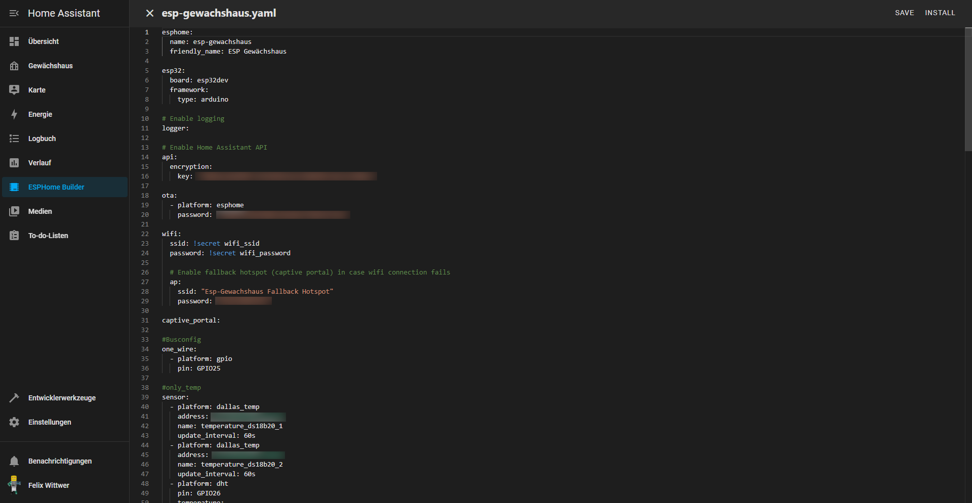
Session 2 (5h)
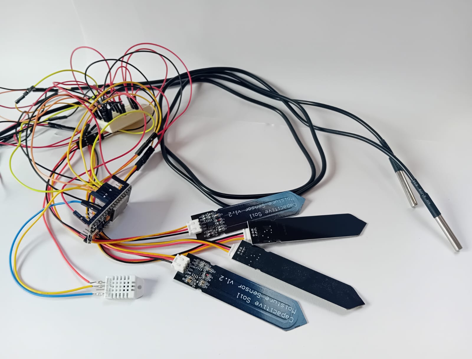
ESPHome is now setup and running with the sensors I currently have. To get it working I put together all the small snippets I already had written for each sensor module. The current setup consists of 4 soil moisture sensors, one DHT22, two DS18B20 soil temperature sensors and a realy board.
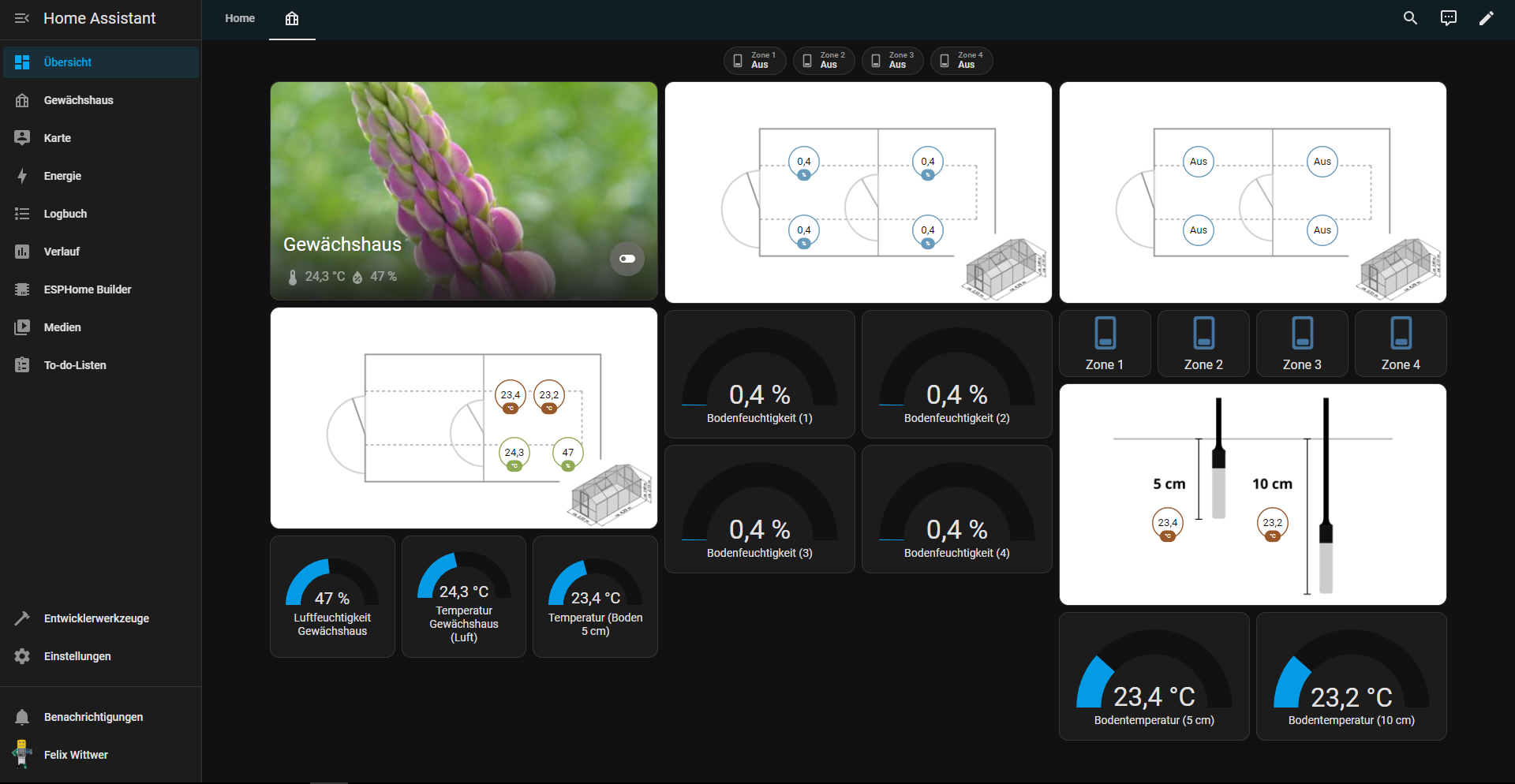
After a lot of tinkering I got a cool dasboard together and it is working! especially styling and placing the sensor values on the map was difficult. It now correctly displays the values of the sensors I have currently set up. Because I have multiple zones for the irrigration and sensors I decided to use Homeassistants stack and map components. A notmal stack of components wouldn't be so resonsive (I want to us it on mobile and desktop and later on maybe on a dashboard) I decided to split things up in collumns and addes some stacks in beetreen that can be easialy resized by the device on the corresponding platform. I kind of fell in love with the dashboard maps and created a floor plan of our greenhouse to get a better Idea where the sensors are located in real life. There is now a map for genreal environment sensors, soil moisture sensors, irrigation system and ground temperature sensors. As a small additon I added small badges at the top of the page to have the irrigation system easialy accesible.
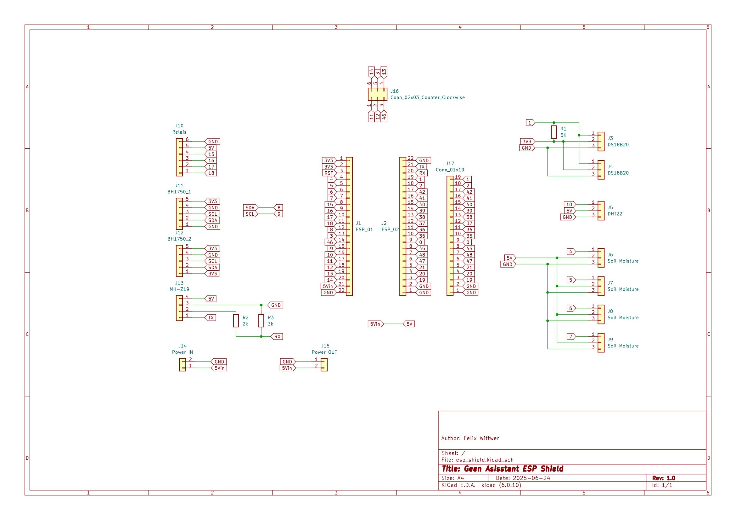
Session 3 (4h): main PCB design
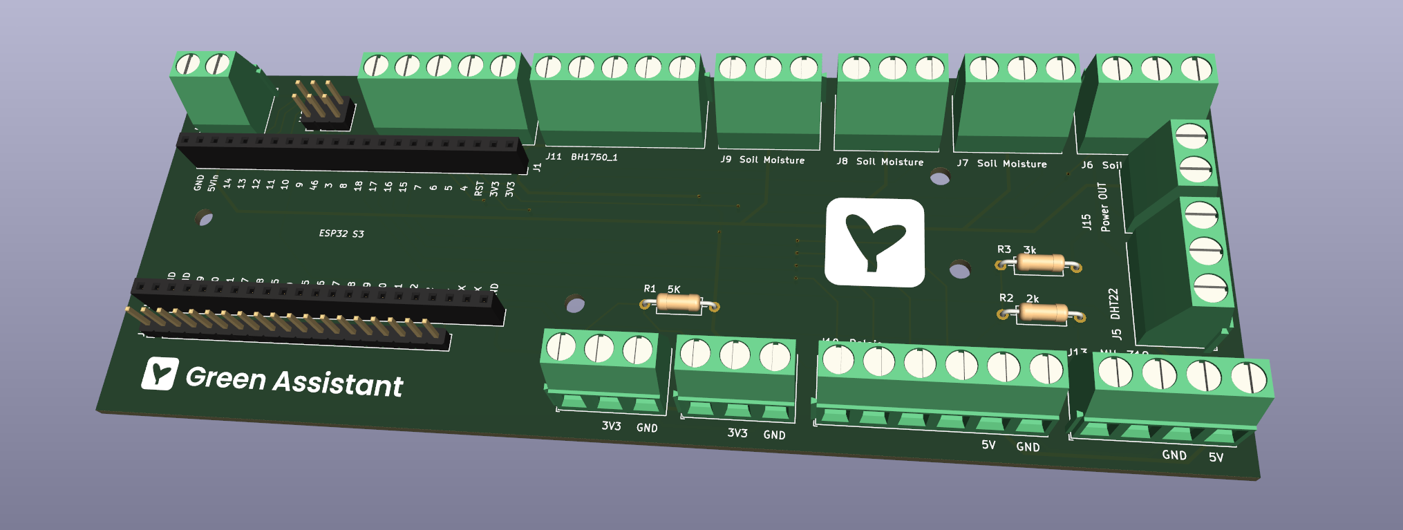
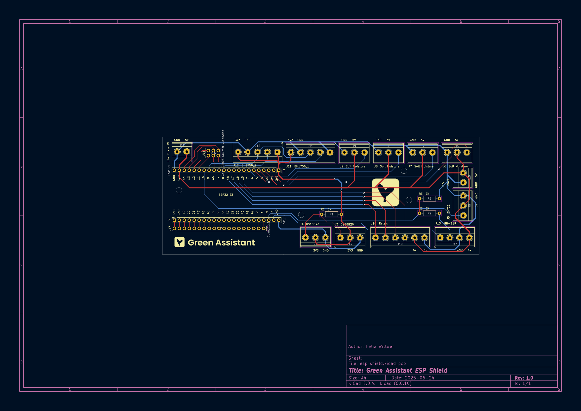
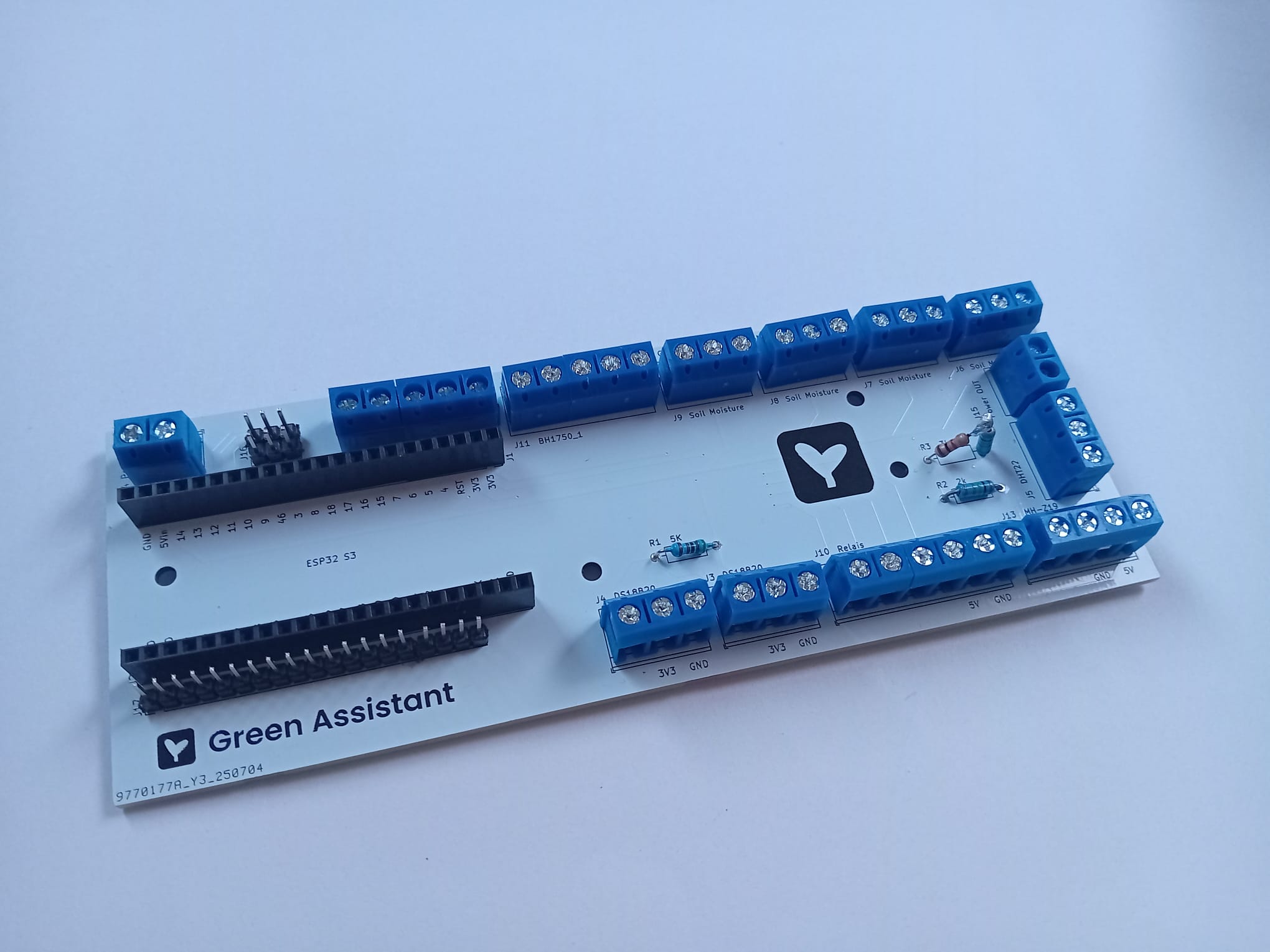
Since my prototype cabeling is an absolute mess and everything should be organized inside the electrical box I designed a shield pcb for the ESP32 S3 I am using. I acutally only need the PCB without assembly because I have most of the parts and from my experience JLC PCB most times does not have screw in terminals with a 5mm pin distance. Furthermore assemby is unresonably expensive for some parts that aren't smd. I intentionally designed the resistors to be non smd so they can be switched if needed. I don't know maybe the very humid enviroment isn't the best even if mostly sealed inside a the electrical box. Additionally I don't know weatcher I need the other pins of the ESP32 in the future so I decided on giving them some headers.
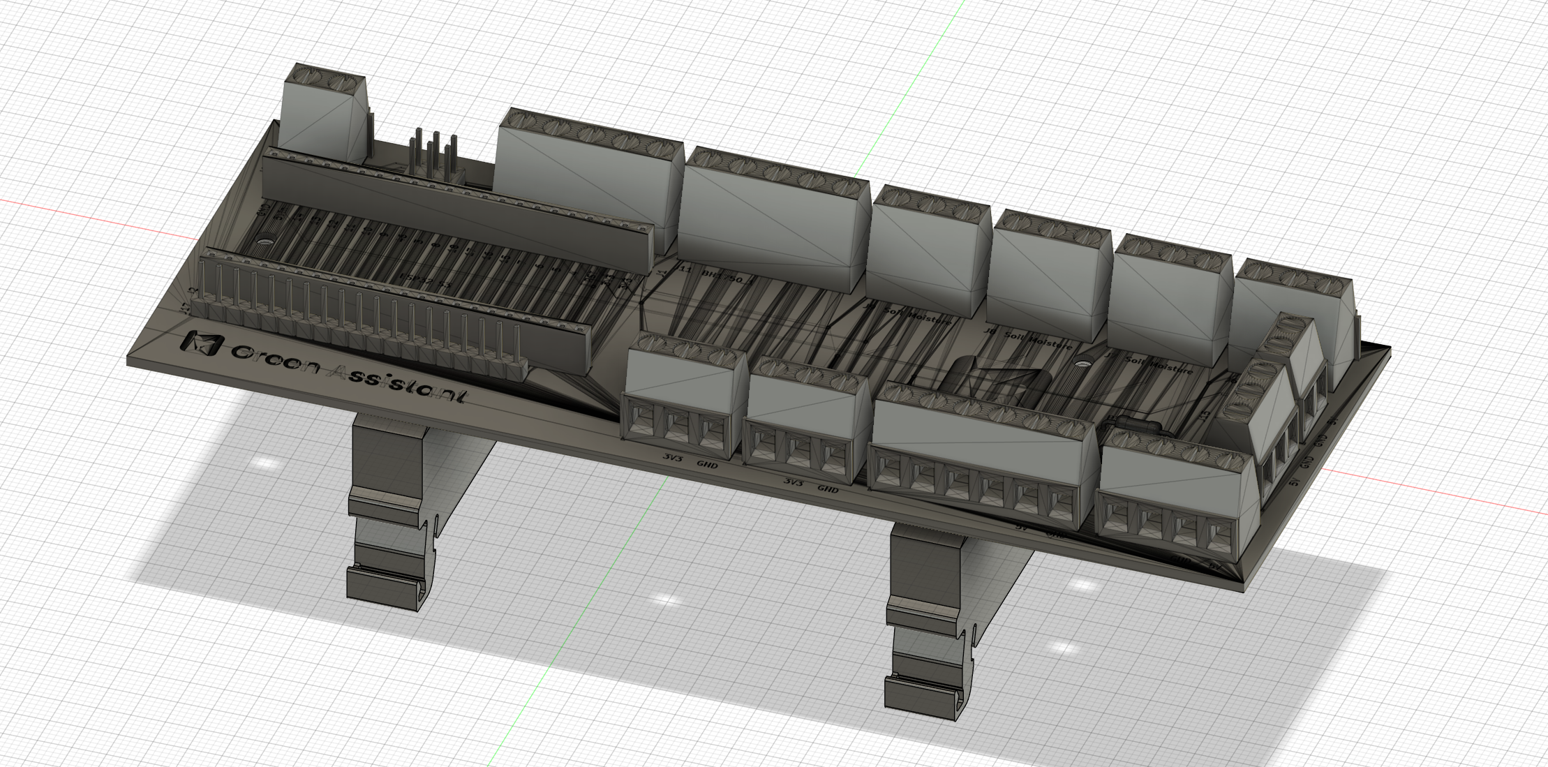
Session 4 (1h): PCB mount deisgn
Becaus the PCB will defenitely wont float and will need some mounting hardware I did just that. If you are wondering how I pulled taht of especially with the random hole design of my PCB (I havent bothered to make something with nice measurements and just placed them here no traces were), I exported the PCB in KiCad to a wrl file and opened that with Blender inside Blender I exported it to an stl file (makre sure to chosse scale 1000 or else your pcb will just be a fractions of milimeters long) and importet this into Fusion 360 where I traced the holes from the stl model.
June 25th (4h): adding irrigation system and finishing of
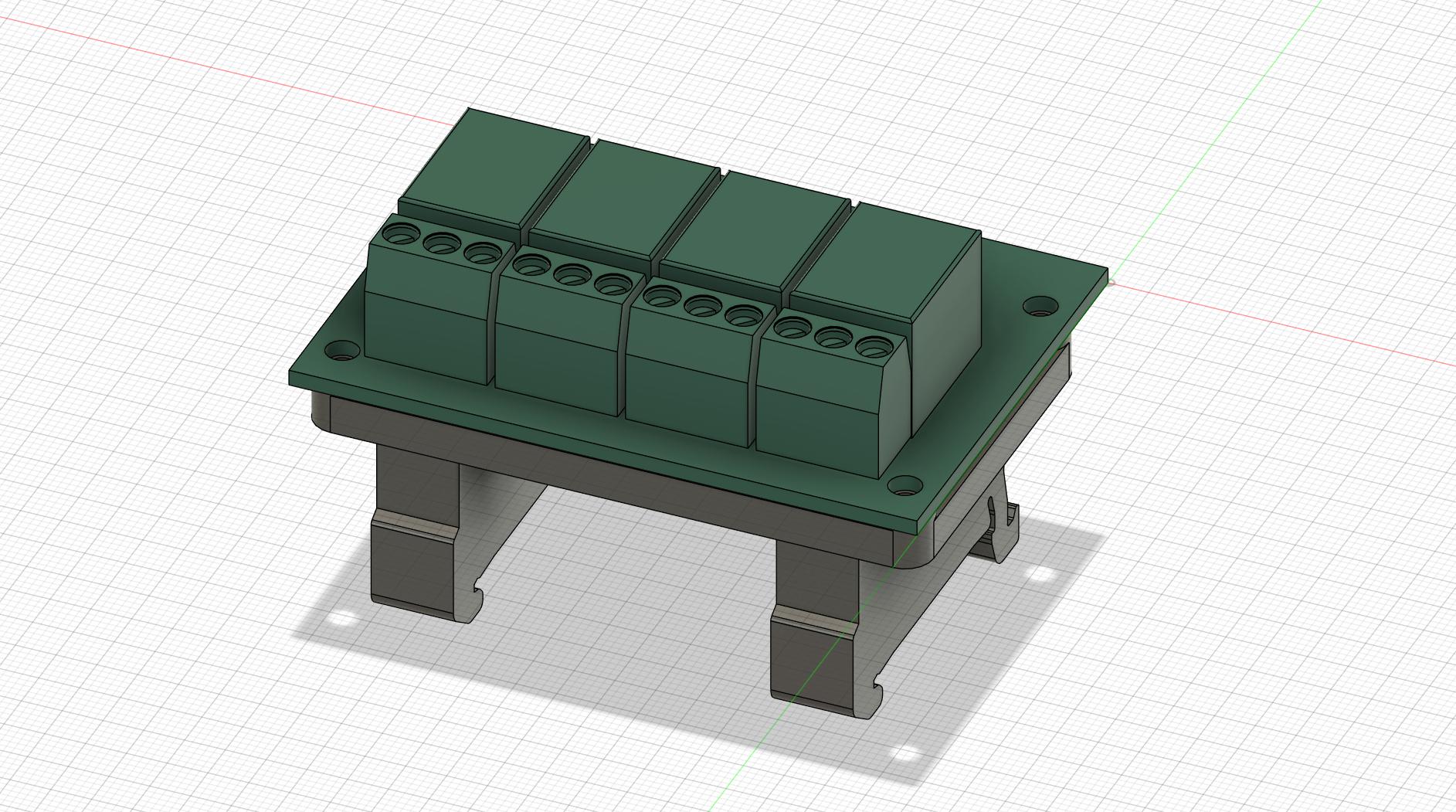
Session 1 (1h): mounting for relais board
My costom PCB already had a mount but to make it perfect also the relay board needed some mounting hardware. In the end I decided to attatch the PCB via 15mm long M3 screws and correspondign nuts.
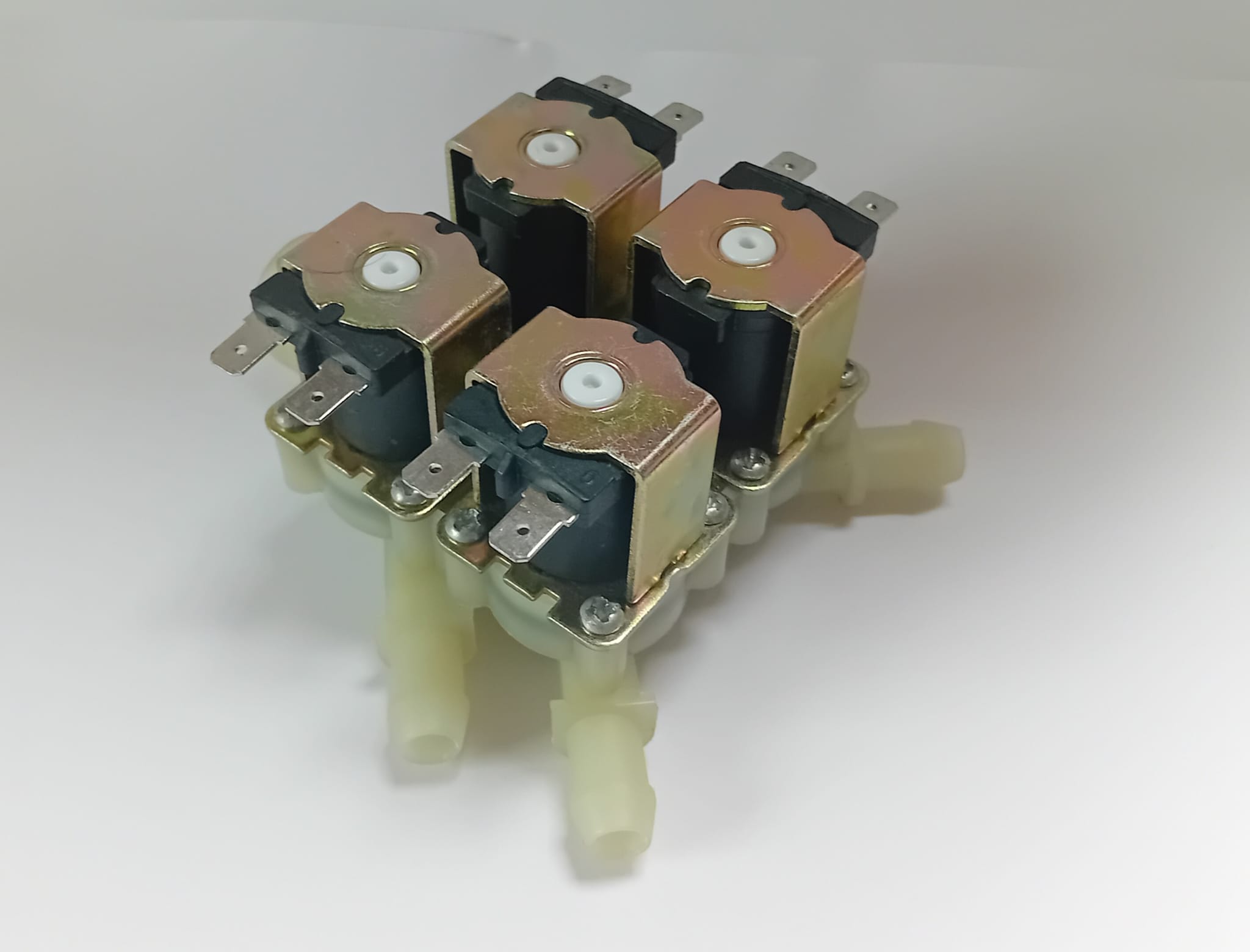
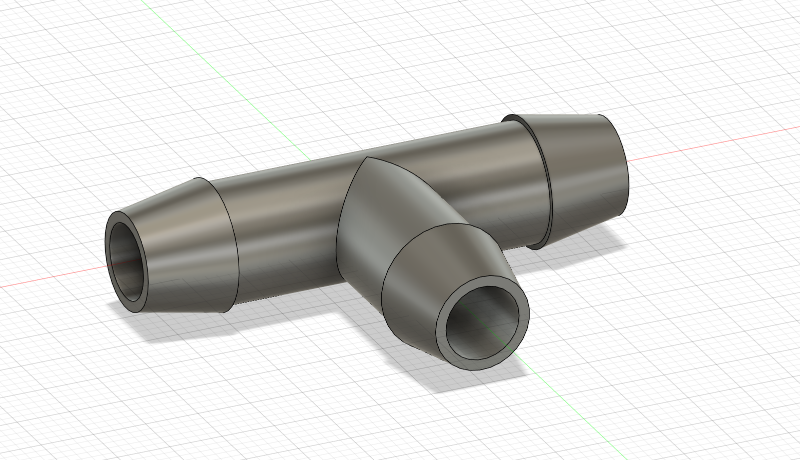
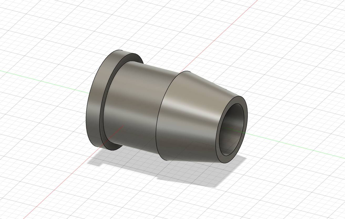
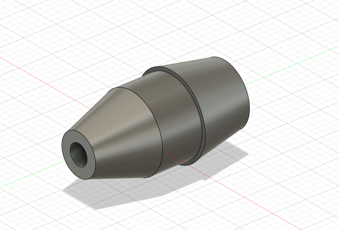
Session 2 (1h): planning for irrigation tubing
Since all electronic parts are done now we have to think of a way to water your beloved plants inside the greenhouse. I decided to go with a 4 in 1 solanid that is perfect for my 4 zone watering system. Between all the components 10 mm PVC tubing will be used. All the individual parts for connecting the individual tube pieces will be 3D printed. So for each plant you need a t piece and a nozzle to water it. I will maybee adjust the nozzle size in the future but for now it should work. Anothe Idea might be to make kind of an l piece at the end to save on the end piece but then the entife l piece nedds to be redesigned and not just the nozzle.
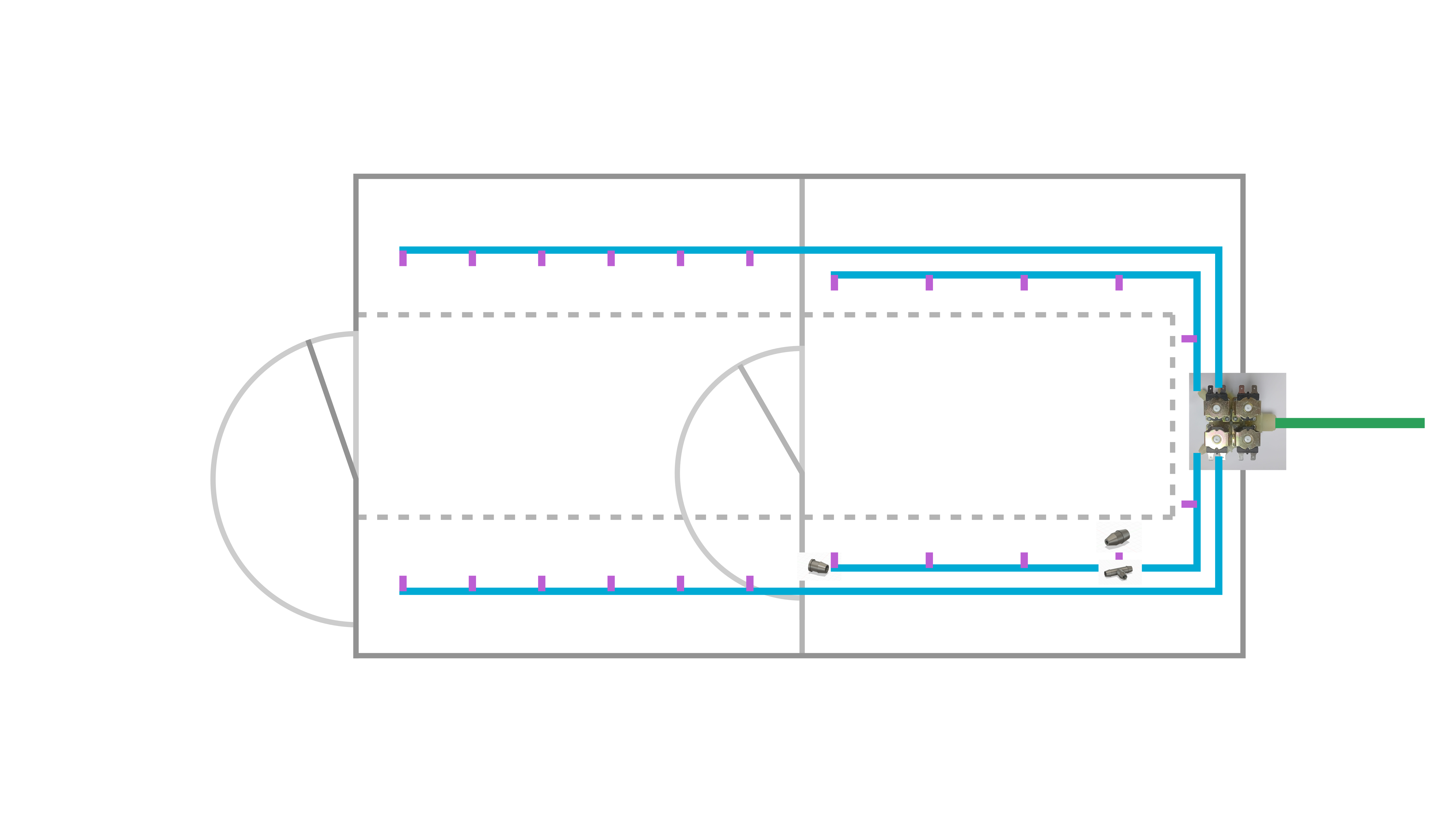
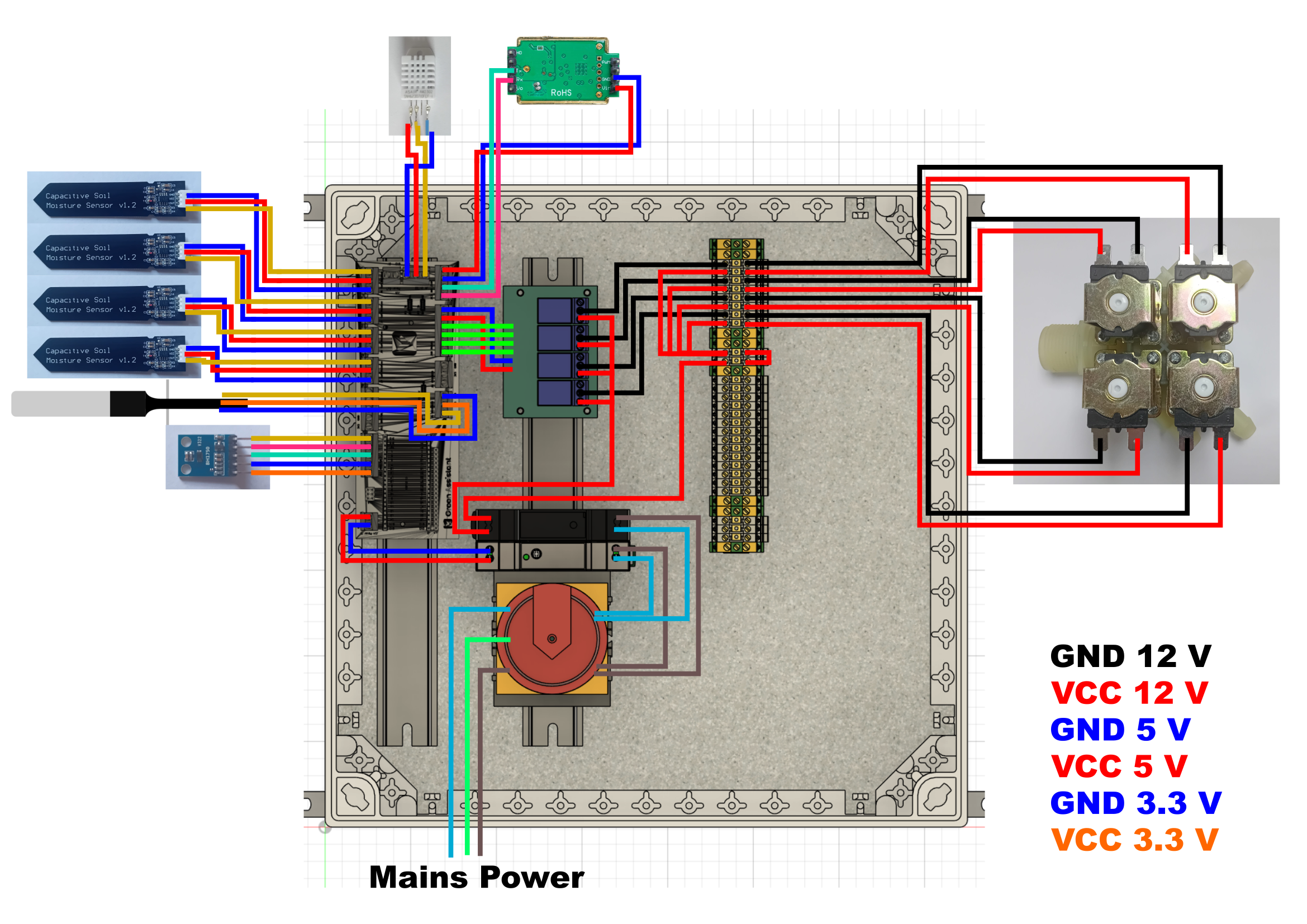
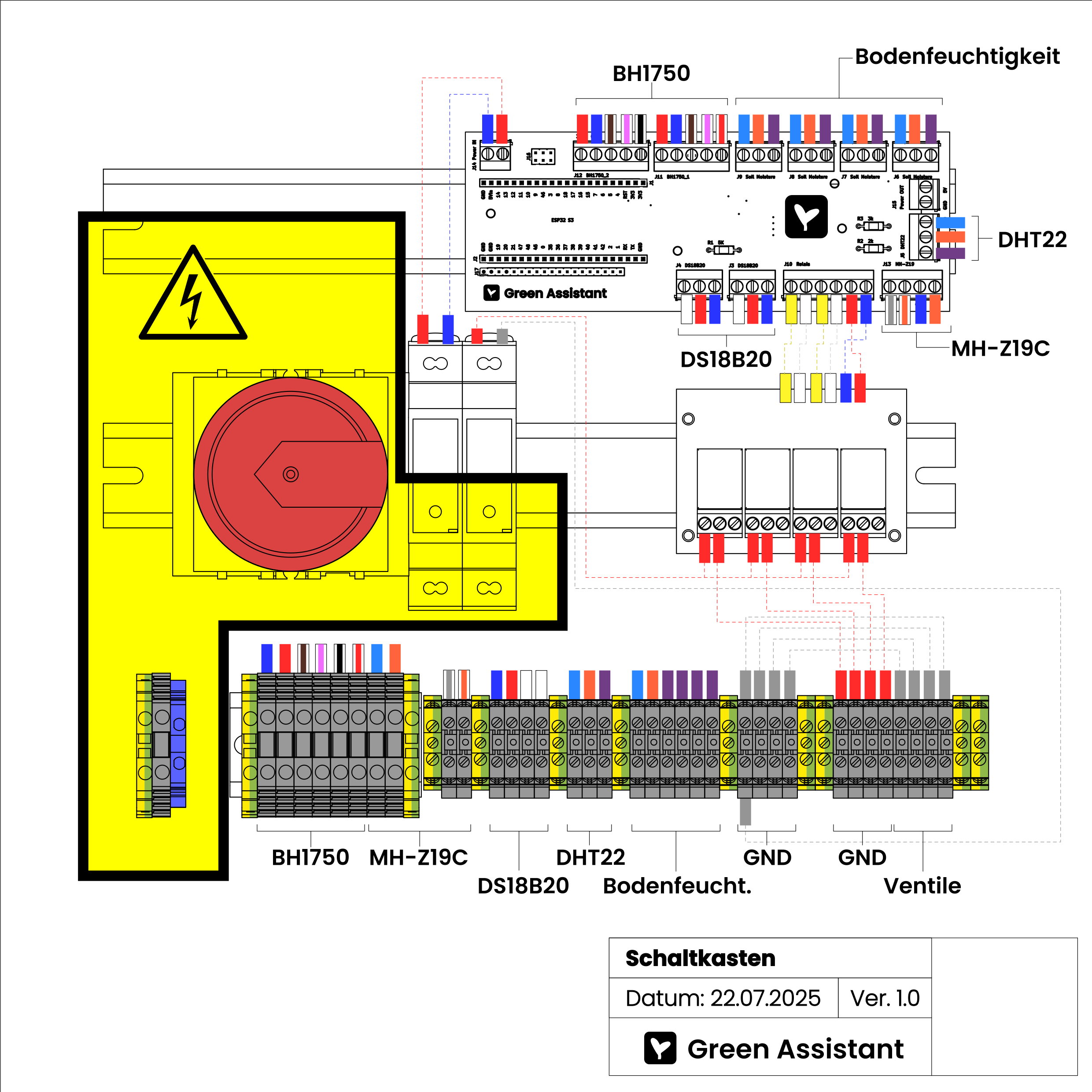
Session 3 (2h): adding a wiring diagramm
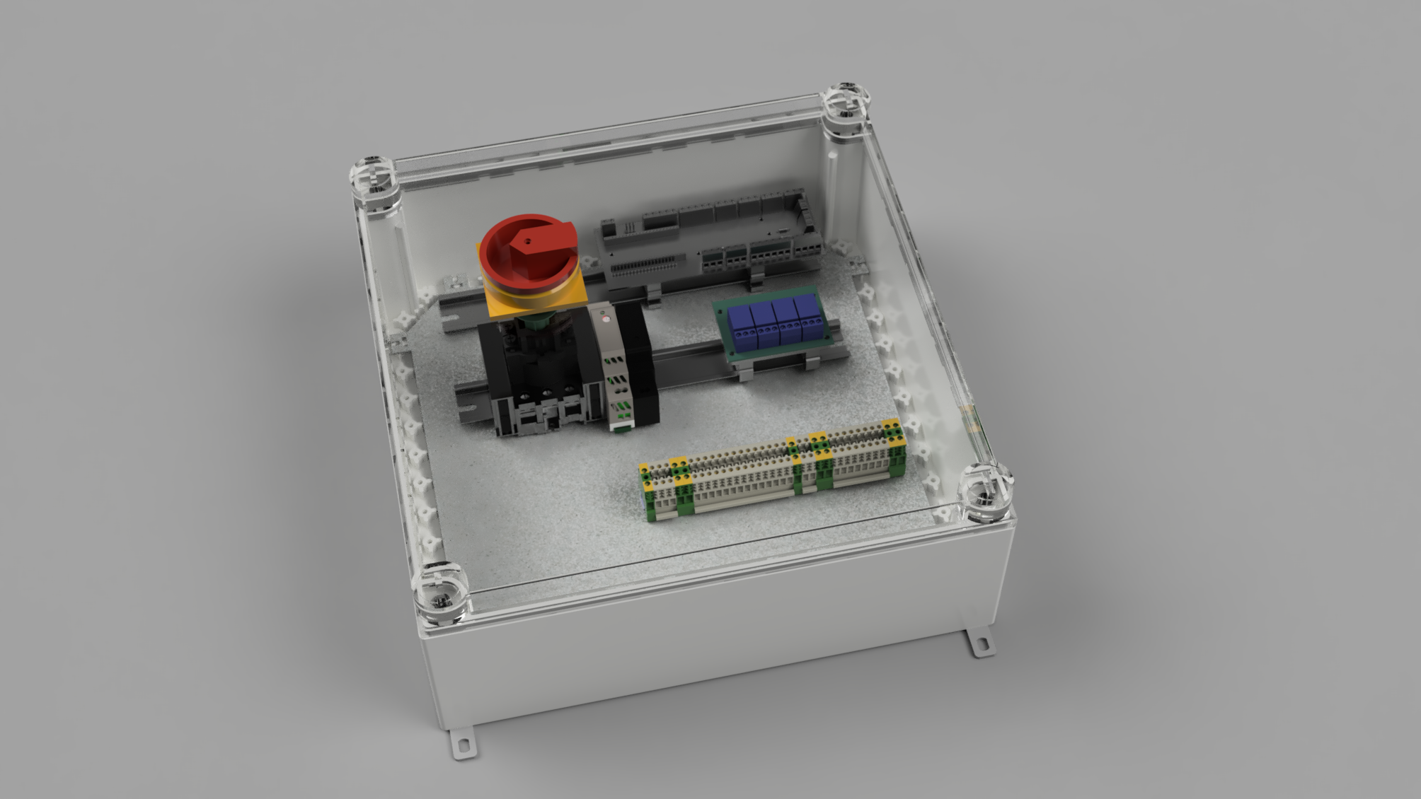
Most wiring is done with the PCB but all the sensor still need to be connected. Here comes the electrical box into play. I am going to use the old already in place DIN rails to mount everything from the relais to the custom PCB inisde. All the sensors will be outside of the box in the places where they need to be. Besides the wiring diagram I finisted the design of the electrical box and arranged its components.
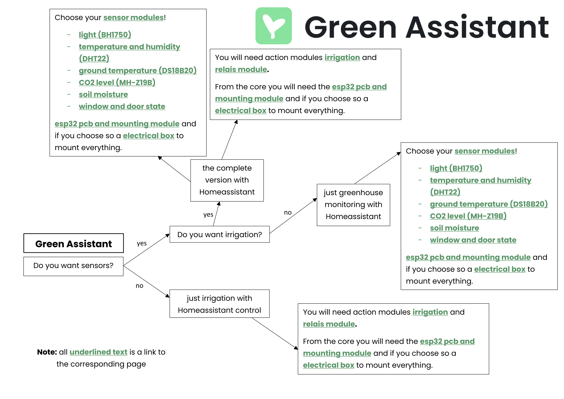
Session 4 (1h): writing some documentation and making it easier to create your custom Green Assistant
Because it could be difficult to understand the projects structure I designed a small diagram on where to start and how to configure your Green Assistant. With this map someone else could easealy start building theor own smart greenhouse. Besides that I extended the main README file a bit.
June 30th (2h)
Session 1 (2h): researching parts and creating BOM
As one of the last steps of the planing phase I finished the BOM list of the project luckily I have most parts of my BOM already at home and also can 3D print parts at home. Fort somebody that is going to build his own system it is imortant to nate that you defenitely don't need a industrial grade waterproof electrical box but we already had one so why don't use it. But for anyone else: you will be fine with buying a DIN Rail and mounting your stuff to it.
Session 2 (2h): doing some final touchups and completing ESPHome config
I have noticed that I have forgotten to add some codesnippets form the individual sensors to the main ESPHome config so I did that now. I have designed and coded all parts for the window and door sensors but forgot them on the PCB. This isn't bad at all because I thought about having all remaining pins pined out so I can add some stuff later on. The PCB has the perfect formfactor and I will not change it now because of space inside the electrical box. The sensors can still be added easily.
July 17th (2h) designing, printing and installing cable clips
To cleanly mount the ethernetwire I choose to the greenhous aluminium extrusions I designed some cable clips that simply could be twisted into the slot. After designing and testing I made a second improved final version. The clips then were printed on my SLA resin printer.
July 18th (1h 30m)
Session 1 (1h) PCBs and parts finally arrived
The PCB and other parts finally arrived today. As a first step I populated the PCB with all the parts. From today on my 3D printer will run constantly to print all the parts.
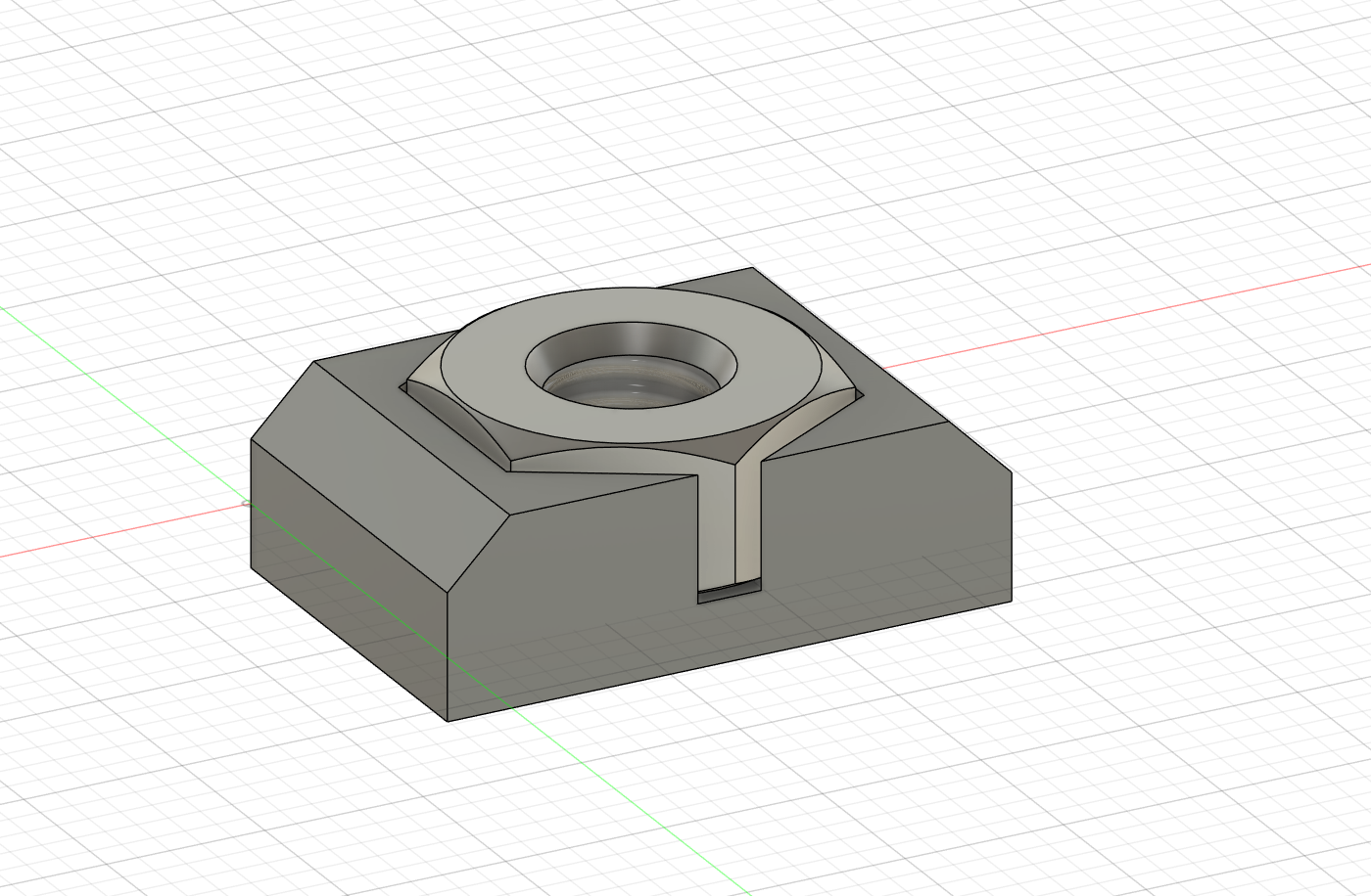
Session 2 (30m) M3 nut adapter
After noticing that the slots inside the aliminium extrusions of my greenhouse are a bit to large to fit M3 nuts I designed an adapter to widen its footprint and stil use the with all the current sensor module designs. This save some time because I don't need to modify all sensor moduels and don't need to buy new screws.
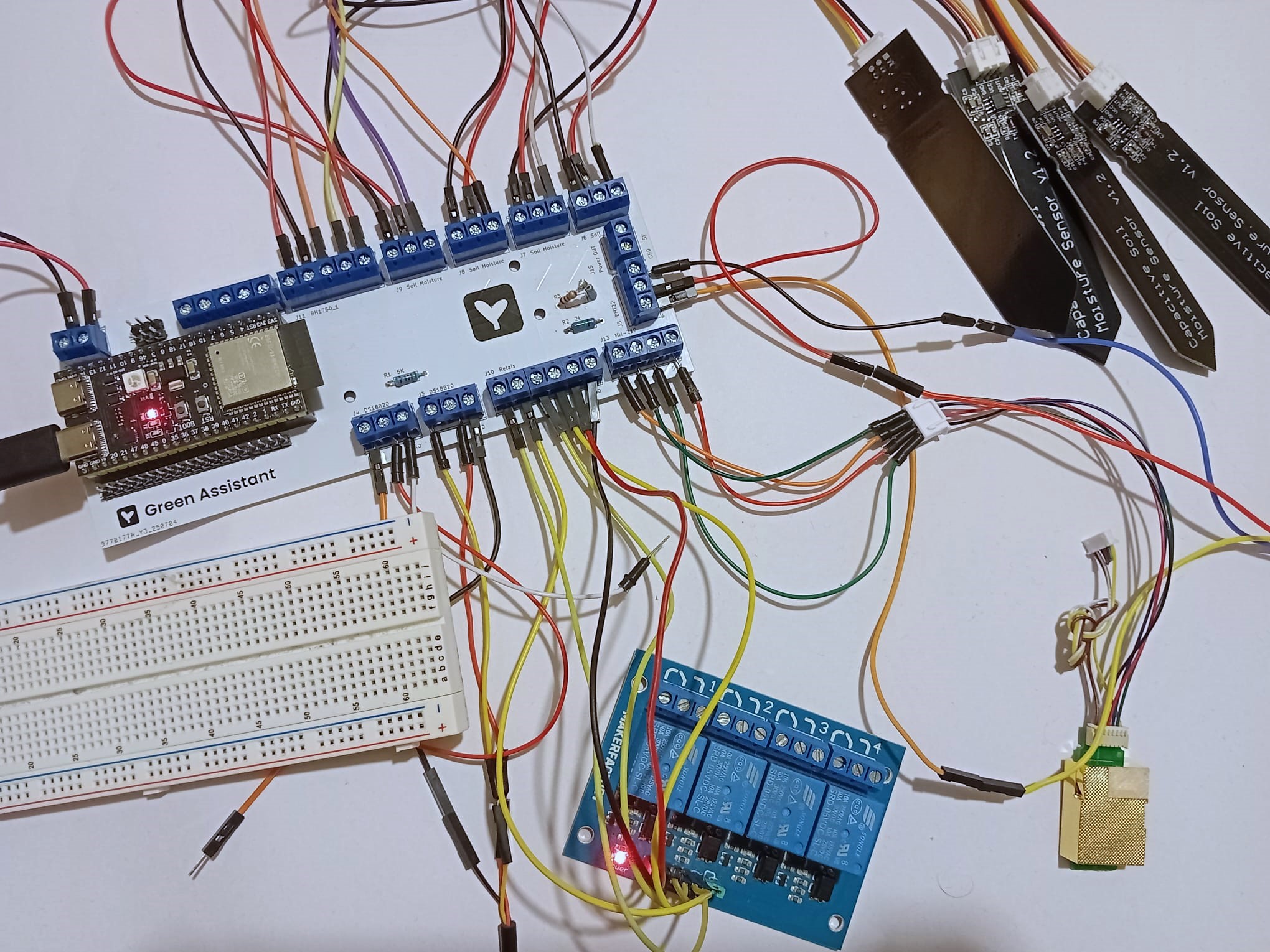
July 19th (2h) testing the PCB
I just finished printing the mount for the CO2 sensor. While the printer was doing its stuff I put all the wires in place to test if all the sensors work. Yeah say so they work now but it took a while to get them work. First of all the PCB needed to be powerd via the 5V terminal which is the case in the final version but not now. took me a while to figure this out but sensors don't work without power :). Secondly the RX and TX pins of the CO2 sensor were labled wrong in the datasheet. And It took me a while to figure that out.
July 21st (4h) start wiring the electrical box
I would have never thought that wiring inside the electrical box takes soooo much time. It tooke me 4 hours now to wire up a good portion of the sensors. The rest of the sensors will be done tomorrow. Besides wiring I also picked up some additional tubing stuff for the irragation system.
July 22nd (6h)
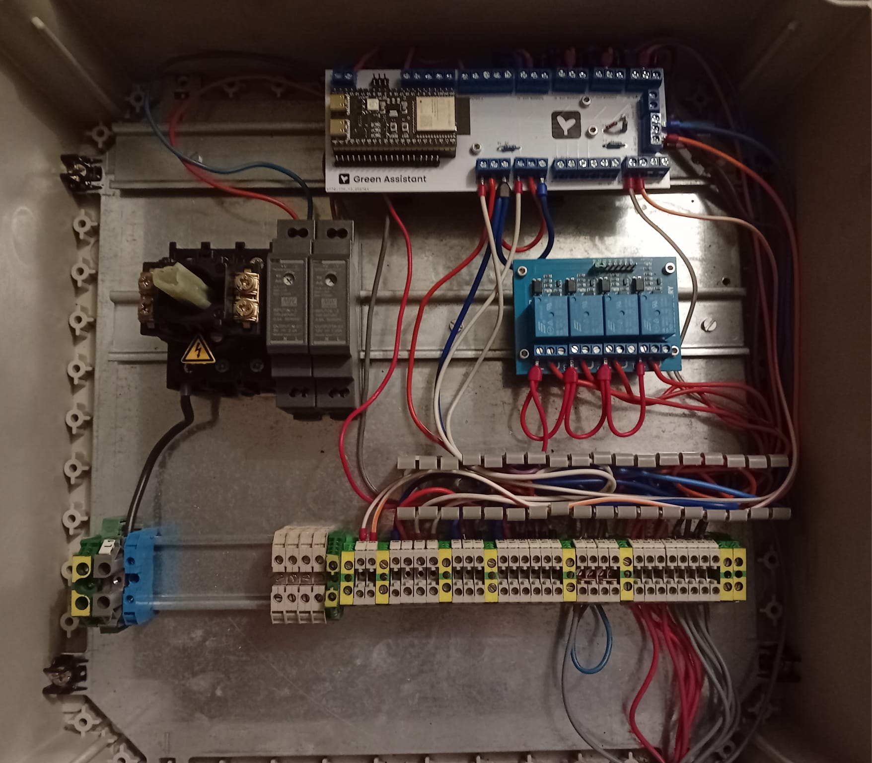
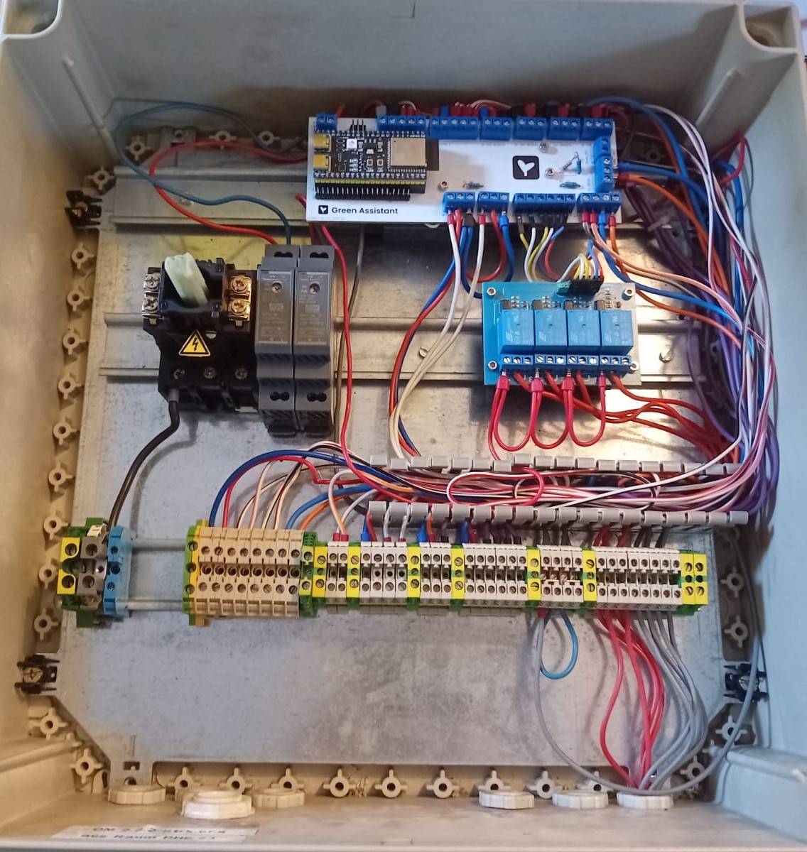
Session 1 (3h) finishing sensor wiring
Today I finally finished wiring all the individual connections from my cusom PCB to the screw terminals whicht are clipped to the most bottom DIN rail. The last step in finishing the electrical box will be to hock it up to mains power and install a standard receptacle plug. After that the sensors only need to be connected via a shielded ethernet cable to the bottom terminals.
Session 2 (3h) start making quick/emergency guide
I now also started to write or actually draw a small manual for the electrical box. So if someone else is going to modify, maintain or expand the system he doesn't get electrecuted immediately. Besides that there will also be a sheet wir instructions on how to turn zhe system on and what the error codes mean. These three to four sheets will be laminated and kept near the box outside.
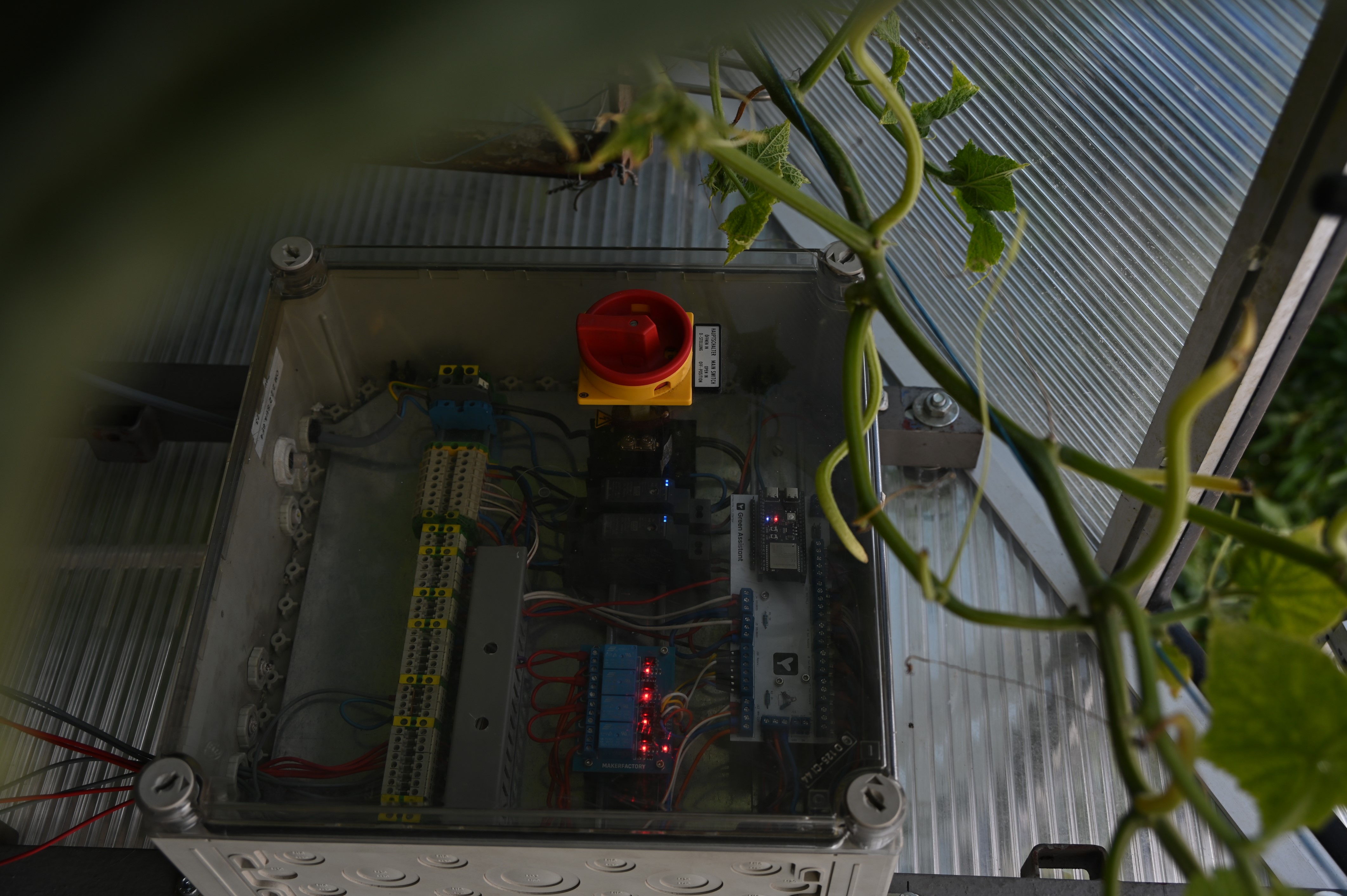
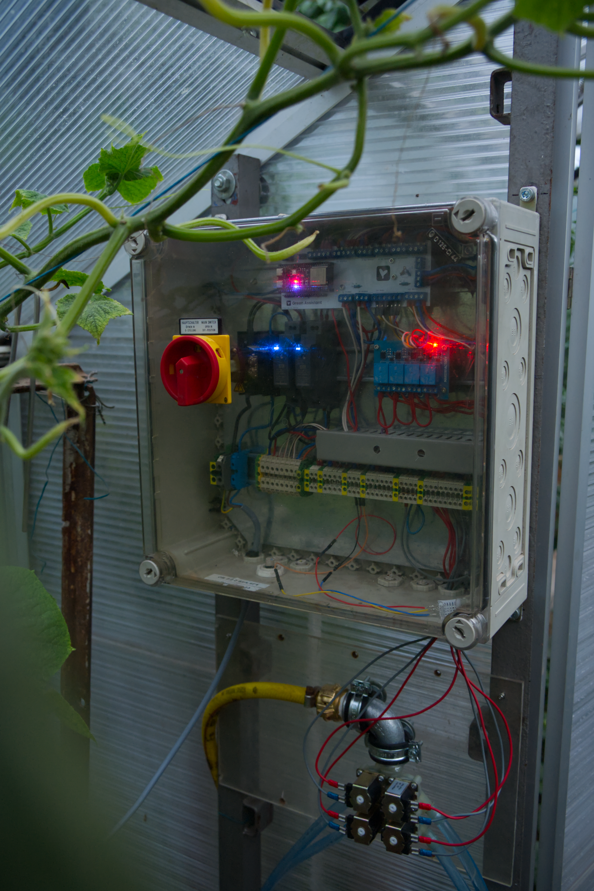
July 23rd (3h) finishing wiring to mains power and install electrical box inside the greenhouse
Finished the last fer wires for connection to mains power and installed the electrical box inside the greenhouse today. Took a bit of time digging two holes for the steel L extrusions. Dirlling the holes tof mounting teh box took sume time due to blunt drill bits :) but eventually found a sharp one which made this step much easier.
July 24th (8h)
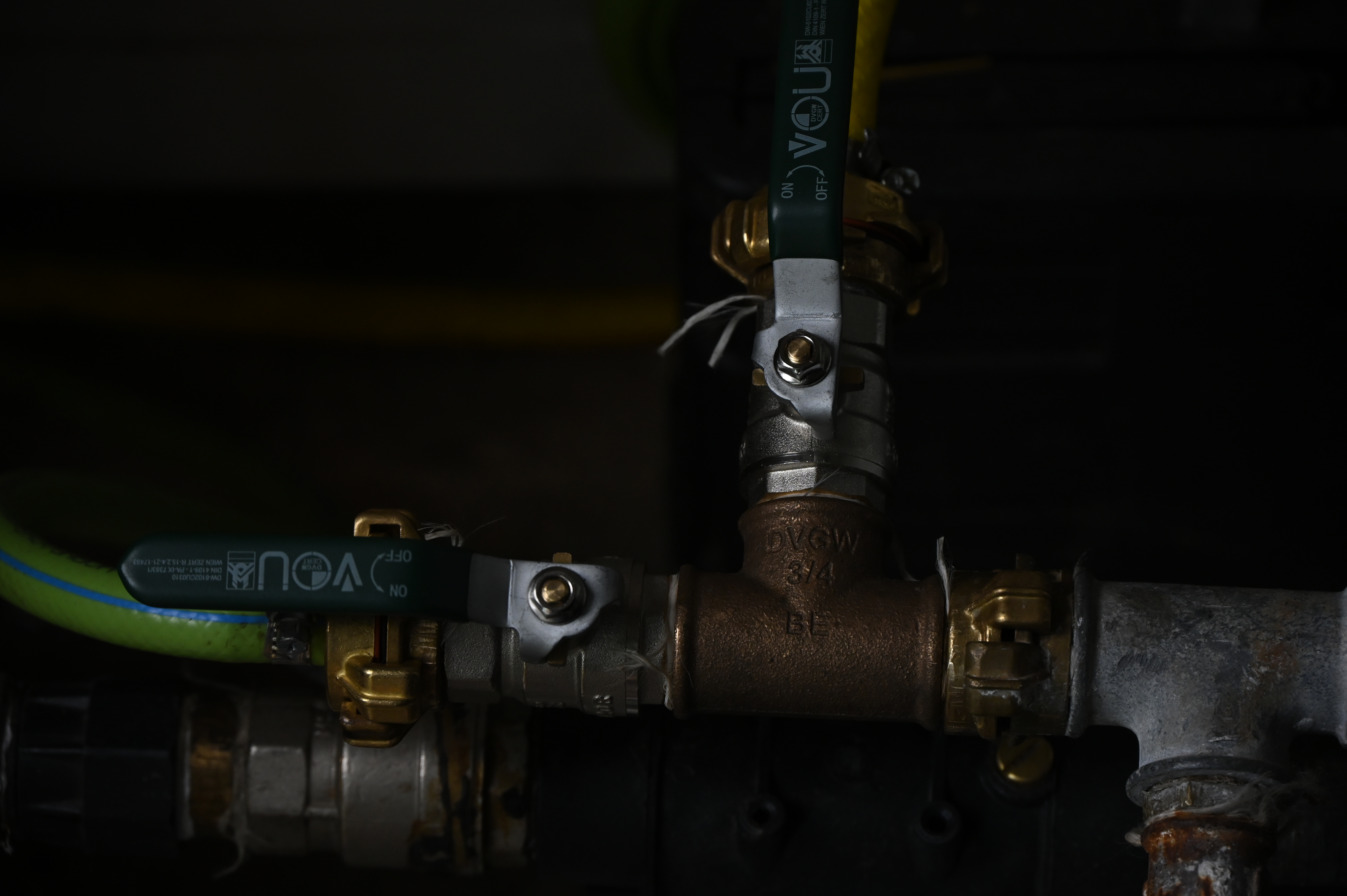
Session 1 (2h) Pluming
So yesterday I finished installing the electrical box. Today I started with laying out a new garden hose from our pump to the greenhouse. To integrate it into our existing garden hose system I needed to build a second howse branch from the existing system which can be shut of with a ball valve.
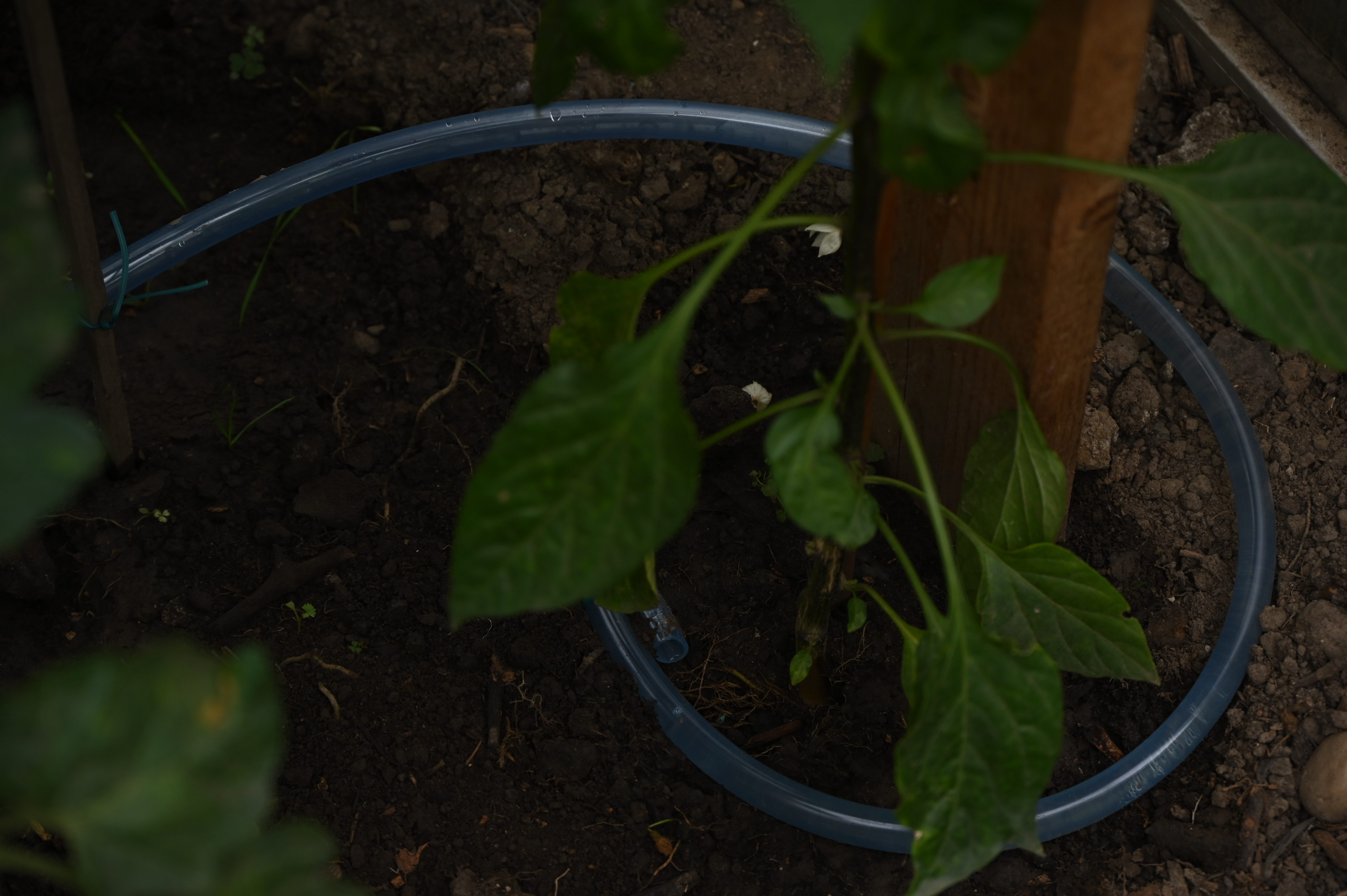
Session 2 (2h) installing the irrigation system
To water all the plants inside thee greenhause I used some simple PCV plastick tubing. Originally I wanted to print T pieces and nozzels for this tubing but went for just tieing it straight to a bar and making some holes with a screwdriver in it. It is defenitely a much easier solution and the tubing is free of additional plastics so it sould be drinking water quality save.
Session 2 (4h) Wiring a few sensors
For my last task for today I choose to wire up some sensors. After making a mistake in the wiring and redoing alsmost verything I managed to get both ground temperature sensors working. Three soil moisture sensors are already connected but dont seem to work properly. But wiring up the remaining sensors and making the sensors work is a task for tomorrow. Maybe a simple calibration could solve the issue.
July 25th (6h 30m)
Status update: Most :) of the installed parts already work perfectliy aka the irrigation system which today run two times perfectly. During some troubleshooting I also confimed that the large shrink tubing with some kind of hot glue in it is actually acually waterproof.
Session 1 (3h) adding soil moisture sensor and CO2 sensor
I succesfully wirde up the last soild mosuture sensor for zone one. Additionally I precut all wires for the remaining sensors and fixed them into place by using my cool twist in clips for the aluminium extrusions. Surprisingly the CO2 seonsor worked from the beginning without any issues. Due to the housing for the light sensor not beeing printed yet I soldered a JST connector on the ent of the wire and sealed everything with some shrink tubing.
Session 2 (3h 30min) troubleshooting
Two of the soil moisture sensors are not working so I cut the shinktubing open to se what is wrong to my surprise the wires seemed to be connected correctly even after coninuity testing it. As I later on found out, the sensors need to be a minimum amount of wet or deep inside the soil and mine werent. After remaking the connections and sealing the sensors with the big shrink tubing they worked. In addition to the harwdere fix I also updeted some parts of the software to accomidate the new voltage levels and correct caluclation of the percentages. In the end I got the soil sensors to work. The soiuld temperature sensors work mostly fine but simetimes the think the soil is at 85°C or has no temperature at all which is defenitely not the case. A reeboot of the ESP resolved the problems everytime.
July 26th (4h) adding light sensor and doing some software stuff
Session 1 (1h) add BH1750
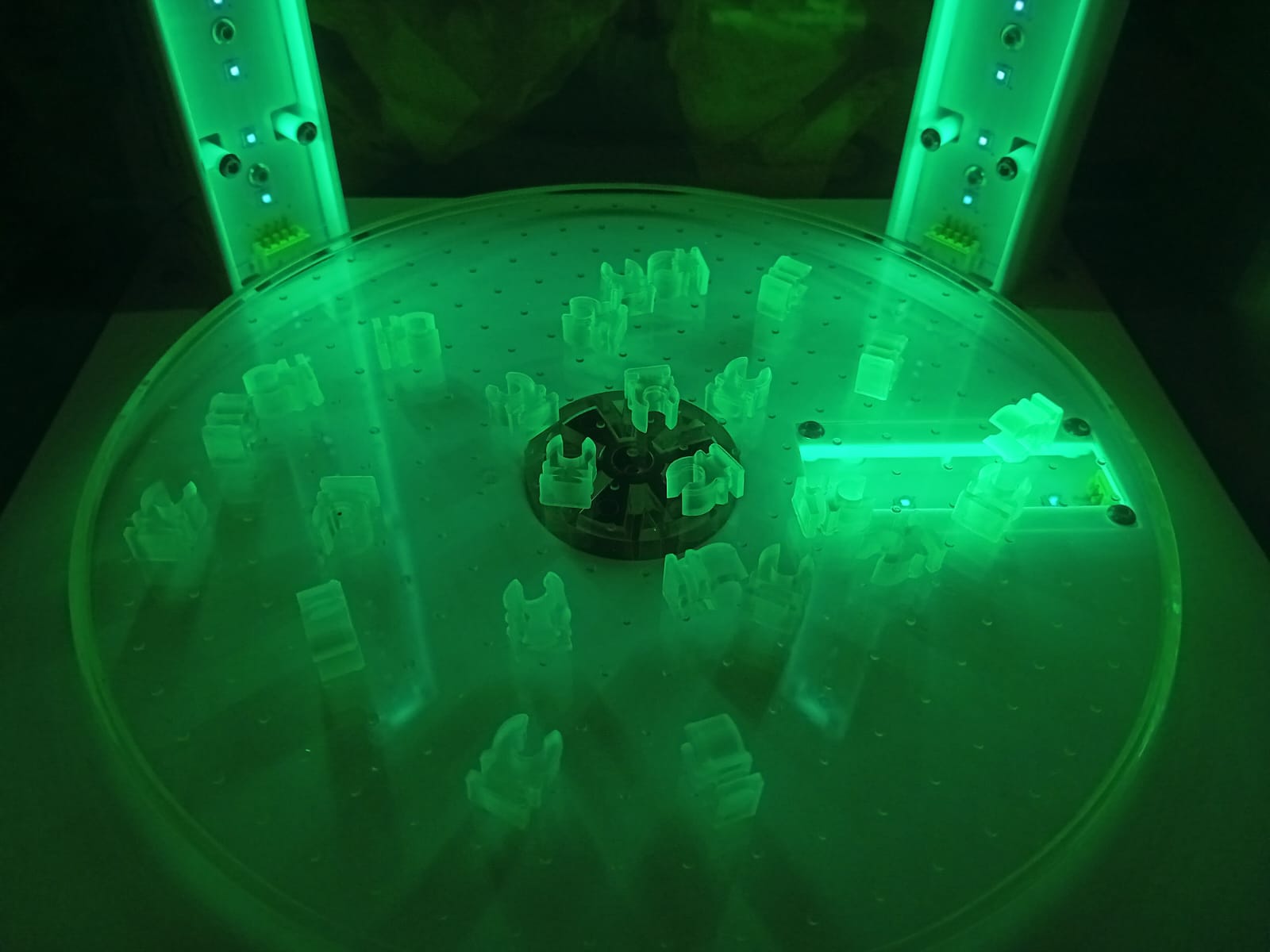
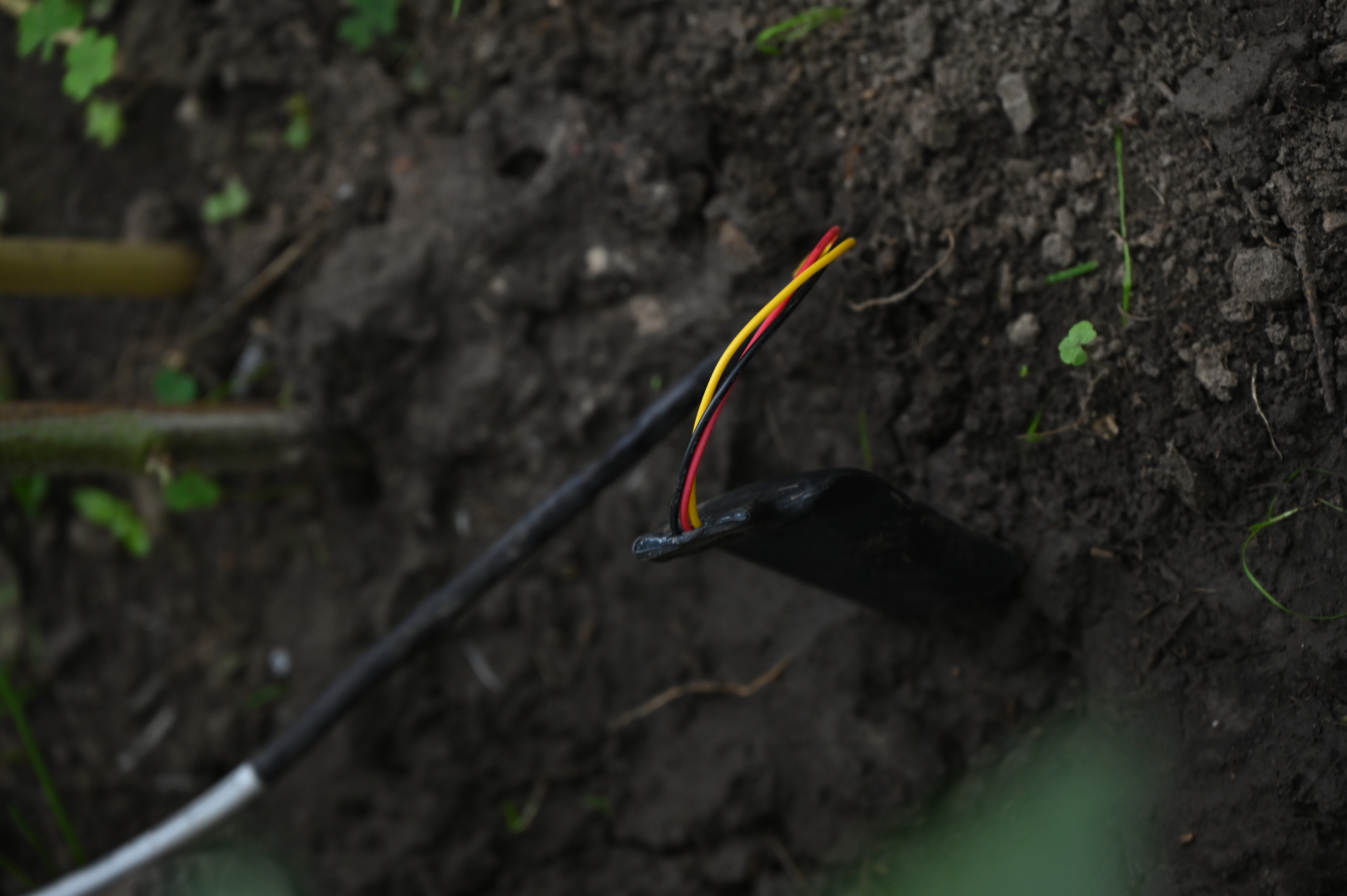
Took me some time to get the sensor working. Turns out I probably wired up everything correctly the first time and was to imapcient to wait until ESPHome fulli registered the I2C connection to the sensor. After lots of trying I finally got it working and the sensor is now providing really nice and clean measurements.
(image before I wired everything up nicely :] in case someone asks)
Session 2 (2h) doing some software configuration stuff
Since the irrigration system is in place now I added a routine for watering the greenhouse for now on a fixed schedule and later in response to the soil moisture data. For now there is a routine for the morning and evening. Both get activated everyday but can be manualld disabled for the day if chossen so. (In case it was raining all day and the soil is still wet)

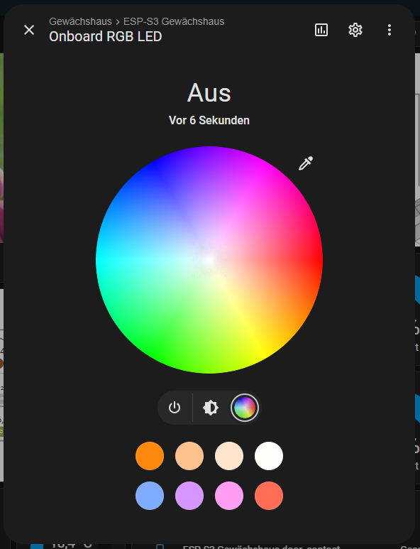
Session 3 (1h) configuring the EPS32s WS2812 LED
For fun and as a future status indicator I wanted to interface the builtin WS2812 on the ESP32 S3. After getting the GPIO Pin right it worked straight away. I can succesfully chnage the brightness and hue of the LED. And say so the LED is pretty bight in the night it can light up the entire greenhous section where the electrical box is located.
August 5th (5h)
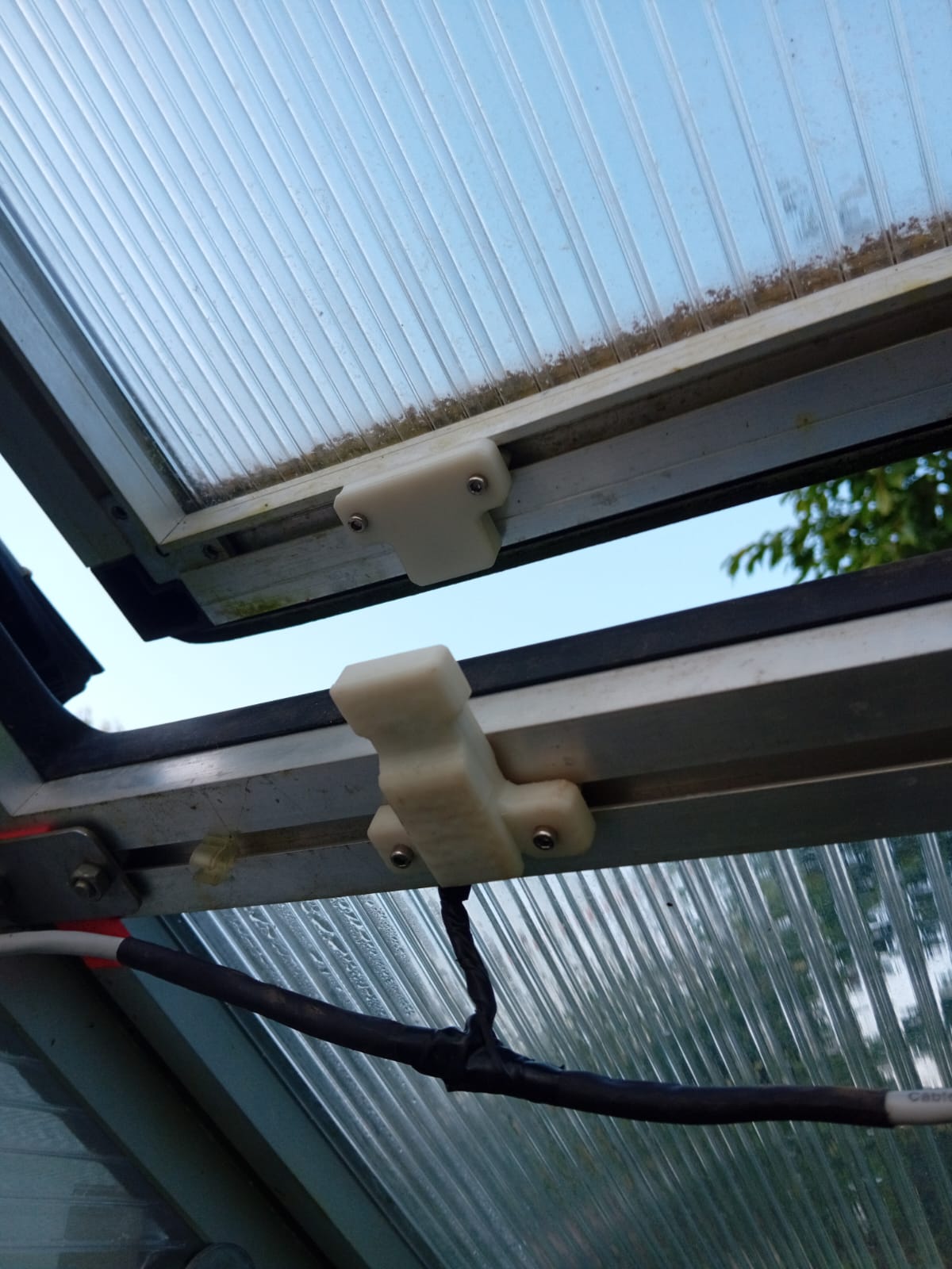
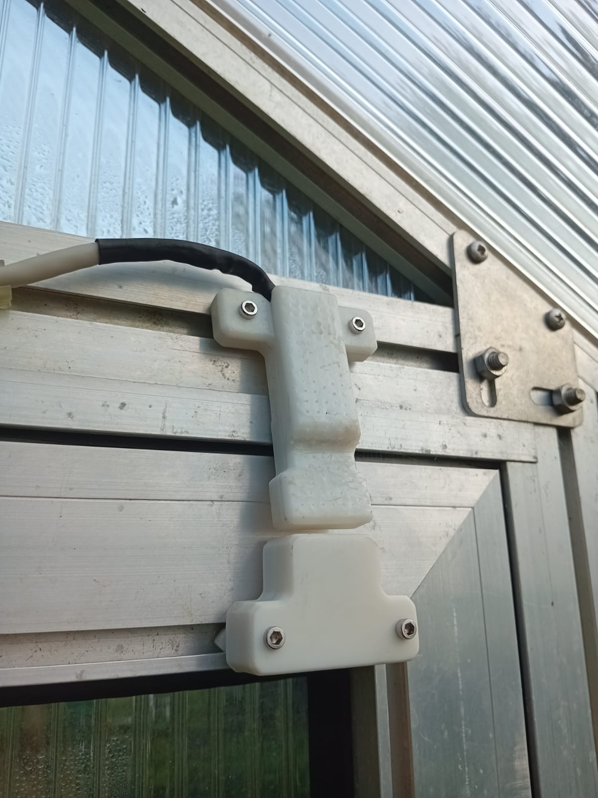
Session 1 (3h) redesigning and printing window and door sensors
I have noticed that my system with the clips on the 3D prints didn't work that well so I designed a new version of the door and window contacts that uses screws (actually the same ones that are already in the BOM). After I finished designing them and needing to make a second iteration that finally worked I started soldering the cable tree for the sensors.
Session 2 (2h) debuging and fixing the sensors
Both of the window sensors worked perfectly on the first install but the door sensor wasn't functioning properly. When first installing it sounded like I cracked the glass ampule of the reed switch slightly and as it turnes out this was the case but it took me a while to notice because you couldn't see the crack direcktly only the resistance values were of as I later discovered. Replaced the Reed and it works now.
August 6th (2h) filming the video and getting ready for final submission
After I finished the sensors yesterday I now only needed the video and a post for the final submission. Video was a bit difficult because I needed to hold my camera in one hand while controlling/ demoing the grennhouse with my smartphone on the other. In the end I managed to film everything and recorded a voiceover.
Reddit post can be found here: https://www.reddit.com/r/Esphome/comments/1mje8r1/yet_another_automatic_greenhouse_but_a_bit/