
Centauri Keyboard
A custom keyboard made to my liking
Centauri Keyboard Journal
May 23rd
The start of a new project, a custom built keyboard down to the PCB.
I Watched this video last night for anticipation of this project. I found it interesting but this video shows you how to build a keyboard but does not explain how it works. It is a good video if you just want to build your own keyboard but I want to understand the nitty gritty of how a keyboard works.
I have thought about what I want this keyboard to look like, here is an image I drew up:
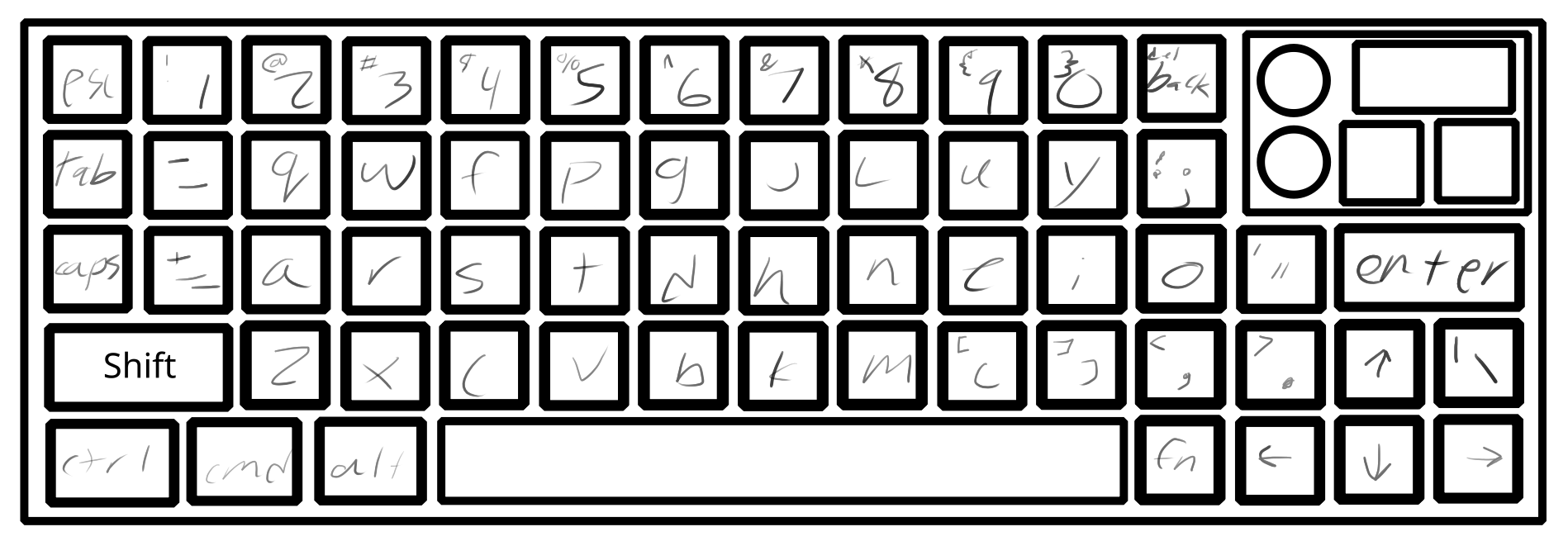 This was a lot of fun to draw up, figuring out where everything should go. There are definitely unconventional parts of this layout going on, like the backslash is in a weird corner but the perk of building my own keyboard is I can change the layout when ever I want (so I can change it down the line). To help with that this keyboard is going to be mechanical.
Since this keyboard does not have a keypad (would just look ugly) on it I feel like I should have another module that is a keypad because I do use it a lot on my current keyboard. I did not create a layout for that but I am thinking just a simple 4x5 size grid.
Layout Explanation
This is a Colemak keyboard layout for the letters but I moved around symbols. I first moved the parentheses down and without a shift since I use them so much, this was kinda my whole notion for the layout is the more I used it the closer it was to the home row. The one thing I do not like about this layout is the size of the backspace button.
The knobs and buttons in the top right corner are going to be programmable so I can change what they do. Kinda like the stream deck with their button and knobs. Lastly there is also a tiny screen I added, that is in the same vein as before.
Time Spent: 2.5 hours
May 25th
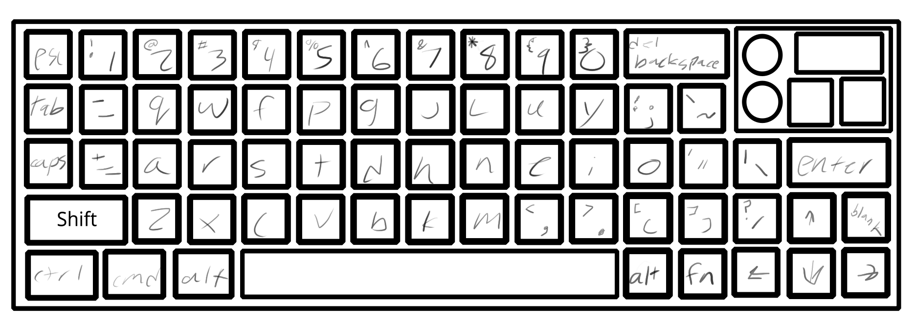
Still on the layout today, I fixed some of the issues that were found. First, there was no '/?' key or '`~' key to fix this I added another column to the keyboard. Second was the backspace button felt too small to me so I made it bigger. Also when it comes to the backspace I will be using function
+ backspace
to use it as a delete key. This also goes for all the F1-10, for F11 and F12 I do not know what I am going to do yet. Lastly there is still that weird extra keys next to the arrow keys that I do not know what I am going to do with (maybe make it an F11, 12 key but that just seems weird).
Here is the image for the updated design:
PCB
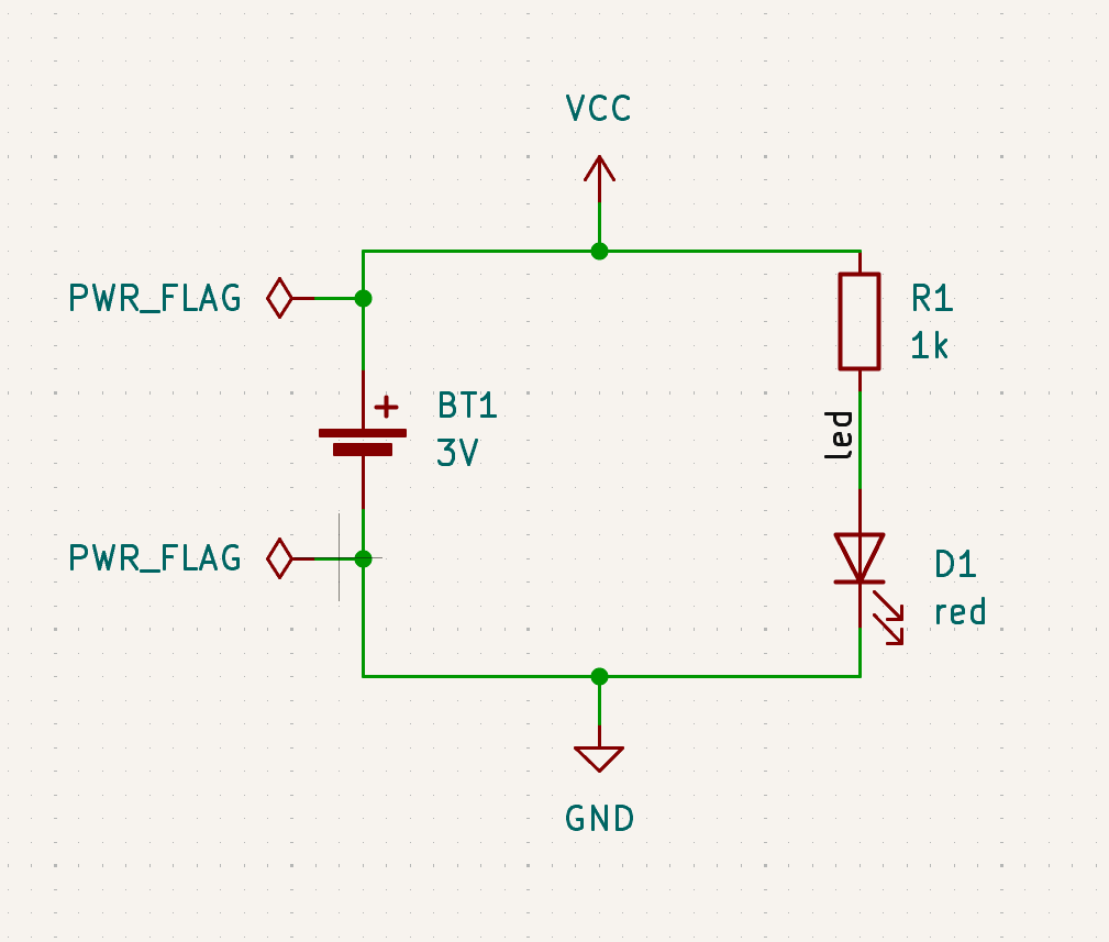
This is my first time creating a PCB, so all I have done so far is reseach. I decide to pick KiCad as my software of choice for no real reason besides that it is free and was the first thing that popped up when I looked up 'how to start making a PCB. I also started the tutorial they have in their docs for beginners. Here is the link to the tutorial. I only got through the schematic:
Time Spent: 2 hours
May 26th
I started today by finishing the tutorial from the other day. I then watched a few Youtube videos on making keyboards in KiCad. Here is the one I found most helpful.
I then proceded to to make the keys to the schematic shown below:
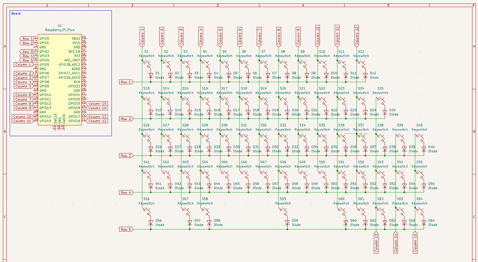 This did not take too long to create, the video is very helpful. One thing you might notice is missing is the special pad in the top right of the keyboard image. The reason for that is once I created the keys thats where I expertise failed and spent the next 2 hours trying to figure out how to do it and researching screens. I am still trying to figure out how to add a screen to the schematic and wire it up correctly. I think I am going to go with a 0.91" OLED Monochrome screen from Adafruit. But the wiring for it is crazy, seen here. It is an I2C display so I have just enough GPIO ports after the knobs.
How this keyboard work is, it will run through each row (whoops, column right now the diodes are backwards), and send a pulse and read what column is high and that will show which key are pressed. The reason for the diodes is to remove ghosting so you press 2+ buttons at a time. Here is a cool website I found explain it. Also going to be using a Pi Pico as the micro controller as it has a lot of GPIO ports, and I am going to be using every single one of them.
Time Spent: 4 hours
May 27th
I did a lot today, I finished the schematic and started on the PCB. Here are the two images I have for them:
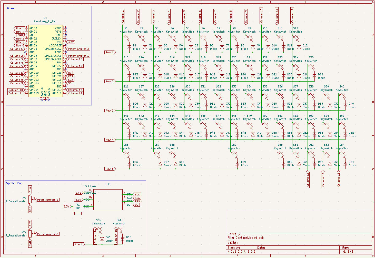
 Looks confusing because it is. I spent so long on the working on everything, they video from yesterday was very helpful. Also switched the diodes around so I now I can do it by rows instead of columns not that it matters that much.
The special pad (thats what I am calling it now) I spent a long time doing the screen figure out which one I want and the screen and it doesn't even fit! I dont know what I am going to do about that. That is a later problem, so I have time to think of ideas.
Some helpful things to know for next time is to figure out all of the hardware before doing the schematics and make sure it all fits. Instead of what I have been doing; researching as I go along. Also I don't think I mentioned this yesterday but the video also comes with schematics and footprints for KiCad which is how I got the switches for the keyboard.
Time Spent: 5 hours
June 12th
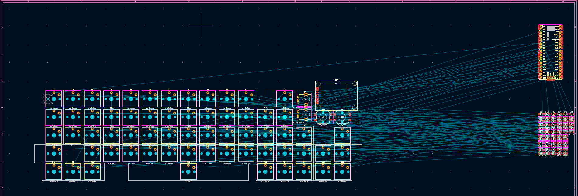
So some time has past, I needed to focus on finals (they went well) but I am ready to jump back into this project. When I say jump I more mean dive because I have been hard at work today. I finished the PCB design!!! Looking back on the last image I now realised how much I did today.
 Some thing I learned when making this was that I need to get better at planning. I had to reroute so many things because I kept changing hardware. And you can tell because some of the traces make no sense and look ugly. I might keeping switching up some minor things but that is it. There was really nothing hard about today, it just took a very, very, very long time to do.
All I have to do now is build the case around it. This should be the easier part for me because you can just export the PCB and build it around that (there is a 3d export you can see an image of it in the README). I also start on the BOM.
Some thing I learned when making this was that I need to get better at planning. I had to reroute so many things because I kept changing hardware. And you can tell because some of the traces make no sense and look ugly. I might keeping switching up some minor things but that is it. There was really nothing hard about today, it just took a very, very, very long time to do.
All I have to do now is build the case around it. This should be the easier part for me because you can just export the PCB and build it around that (there is a 3d export you can see an image of it in the README). I also start on the BOM.
Time Spent: 8 hours
July 6th
Wow it has been awhile since I have worked on this project. What I have done today is built the case for the keyboard and did more research on the money.
First the case, I have no idea if I built it write, I am not very good with CAD so when I actually start building the keyboard I might need to change some stuff but I will update the github page. This is what I have as my final
case build. I would add the full file but github likes small files and it is not, so I only uploaded the case and the plate (which is all you really need)
 Now with the money I found that it is going to be more than the $150 but I will just be using my own money.
Since I have not touched on this yet I am going to be KMK.
Now with the money I found that it is going to be more than the $150 but I will just be using my own money.
Since I have not touched on this yet I am going to be KMK.
Time Spent: 4 hours