
CFWatch
It's a watch! But custom! Wow!
CFWatch Development Journal
Total time spent: around 25hrs
Session 1
And so it begins! The goal here is to build a watch I'd genuinely be happy to wear daily, with non-intrusive charging circuitry and decent battery life. I've been loving the posts in r/cassettefuturism lately, so something fitting that vibe would just be awesome to build! I'm leaning towards 7 segment displays rather than one of those cheap 0.96" oleds or a round LCD/TFT display, simply because in my opinion they look a lot less cheap and can convey what I need them to easily. I think the main challenges here are going to be durability, making something that doesn't cost a fortune to assemble, and driving displays from a microcontroller. Here are my current ideas: - Something like the KCSC02-105 for a surface-mounted 7 segment display - Possibly a nRF or SAMD21 microcontroller for low power usage - A LIR2032 rechargeable button cell for the battery seeing as the CR2032 in the same form factor is super popular and has a lot of mountings available
Here are some designs that inspired me:
| 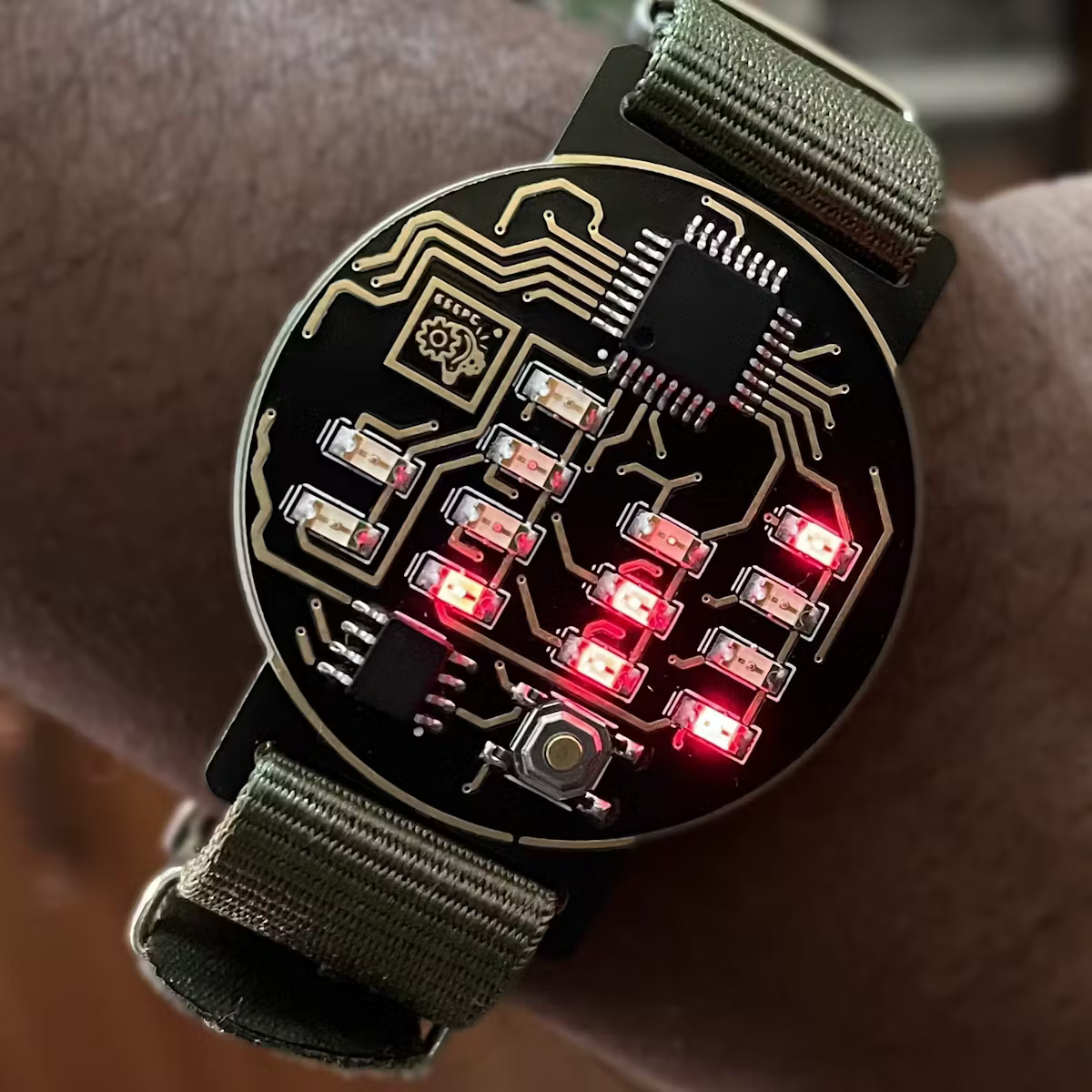 |
| 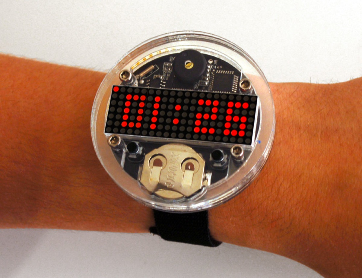 |
| 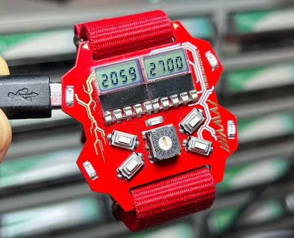 |
| :----------------------------: | :----------------------------: | :----------------------------: |
| Cool binary display | LOVE this LED matrix!! | USB and very nice displays |
|
| :----------------------------: | :----------------------------: | :----------------------------: |
| Cool binary display | LOVE this LED matrix!! | USB and very nice displays |
I've created a schematic in this session that I'm fairly certain is a good starting point, but it is definitely subject to change a lot! I included: 1. A battery and charging circuit using the MCP73831-2-OT 2. A USB C port with the appropriate resistors for 5V input 3. A 5V-3.3V step down with the AP2112K-3.3 (the SAMD21 uses 3.3V) 4. 4x 7 segment digits with transistors to select which digit is active - these are charlieplexed to reduce pins necessary to drive them!
I made it by breaking down the design into smaller chunks, with the first challenge being power regulation. - The SAMD21 uses 3.3V power, whereas a LIR2032 cell gives a wide range and USB-C typically deliver 5V as a standard. I solved this by having the USB and cell feed into a step down converter as mentioned above, supplying a steady feed to the MCU - The displays themselves are charlieplexed using 4 transistors, each selecting a digit and allowing it to be driven. I'm sure this will be difficult to manage in software, but that's a problem for future me :) - I've never really done much with a bare metal microcontroller before, so I did quite a bit of research on how to power them; the datasheet for the one I'm using said to add capacitors on all the power lines, and I used diodes too just as a precaution to prevent anything being fried by reverse polarity - Another fun issue is actually keeping the time; to save space I really didn't want to add a whole RTC, which meant I needed the internal clock of the MCU to be as accurate as possible. How did I do that? Adding a crystal! I won't pretend I didn't use a ton of references from other people's projects here, since I have never paid attention to crystals in schematics before so haven't a clue how they should be wired KiCad's labels are severely underrated too, this whole schematic looks really clean, but I would never have managed it without them!
I made a significant chunk of progress in this first session, but a lot will be changing as I learn more about how to design a project like this!
(session duration: ~6hrs!)
Session 2
It's time for laying out the PCB! I once attempted to make a PCB watch before, but it ended up being very expensive to order from JLCPCB because it required double sided assembly, so this time I wanted to keep everything but the battery on the front. Here's what I ended up with:
And prepare yourself for autorouter torture!
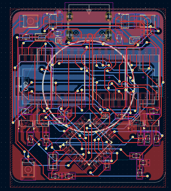
I also changed quite a bit in the schematic; first of all I switched the resistors for the displays to be in series with the common anode rather than for each segment, gaining me valuable board space. I have the SAMD21 at 45 degrees to make it easier to route and also fit on the watch (which ended up being about 35x40mm in this revision)
(session duration: ~4 hrs)
Session 3
What's one important thing this watch is missing? Probably a case! I've been putting this off since I'm completely new to CAD, but this is a great time for me to learn. Initially I tried OnShape before quickly learning I did not enjoy using it at all, and switched over to FreeCAD, which when it isn't randomly crashing is an excellent piece of open source software! Getting the hang of constraints wasn't very easy, but once I got my head around it they did make quite a lot of sense. I also exported a .wrl of my PCB from KiCad and a STL from FreeCAD to check they fitted together, I've added a render below:
This was really interesting to play around with, and I learned a ton about CAD in the process! The main issue I faced was with the battery cell - almost every mount for a CR2032 cell (I'll be using a compatible but rechargeable LIR2032) was at least 4.5mm tall, which makes it difficult to design a case without it being super tall.
(session duration: honestly I split this into a few sections and completely lost track. Maybe 6 hours total?)
Session 4
This session was mostly focussed on cleaning up the watch and readying it for production. I did this in about 3 sessions in reality, but since they were all pretty similar I'll write it up in one. Enough preamble, let's get into it! The first thing I did was to get some sensible footprints assigned. Turns out, using 0603 for everything was a stupid decision - especially for diodes. I did have to use small footprints for nearly everything, since 4x4cm is pretty tiny in the grand scheme of things Next was routing vias... turns out, autorouter sucks, especially with such a tiny board. I routed it all by hand which led to something a bit like this:
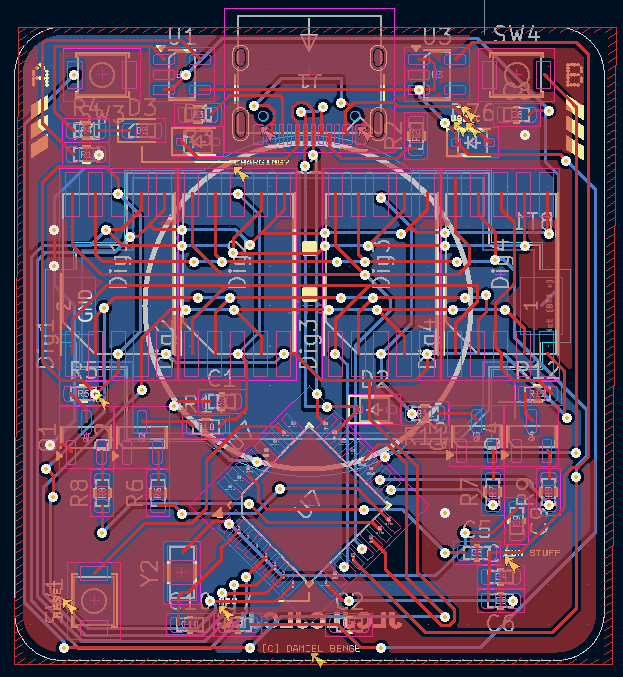
The main issues was that the 7 segment displays made it really hard to route anything near them since they hard 10 pins each. I had to increase the board size by a few mm too, just to make enough room for traces near the edges, and I added the JLCPCB order placeholder on the back too. The main reason everything was so difficult to lay out was that to stay under my $150 budget, I had to keep everything on one side of the board to save the $50 fee JLCPCB adds for double sided assembly (which is fair enough really, I can't imagine it's easy to do with a pick and place machine)
With that done, I moved on to the case - since I changed the board shape I needed to update the 3d model. I increased the size a little, and rounded the corners more to make it much more aesthetically pleasing/
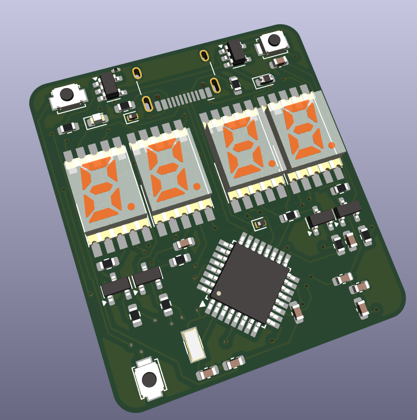
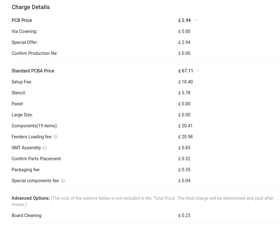
Okay, almost done now! I uploaded this draft of the design to JLC to get a rough estimate of the cost, and it came out to about £70 as shown below. Personally I think that's a pretty amazing price when you consider how difficult assembling something like this can be!
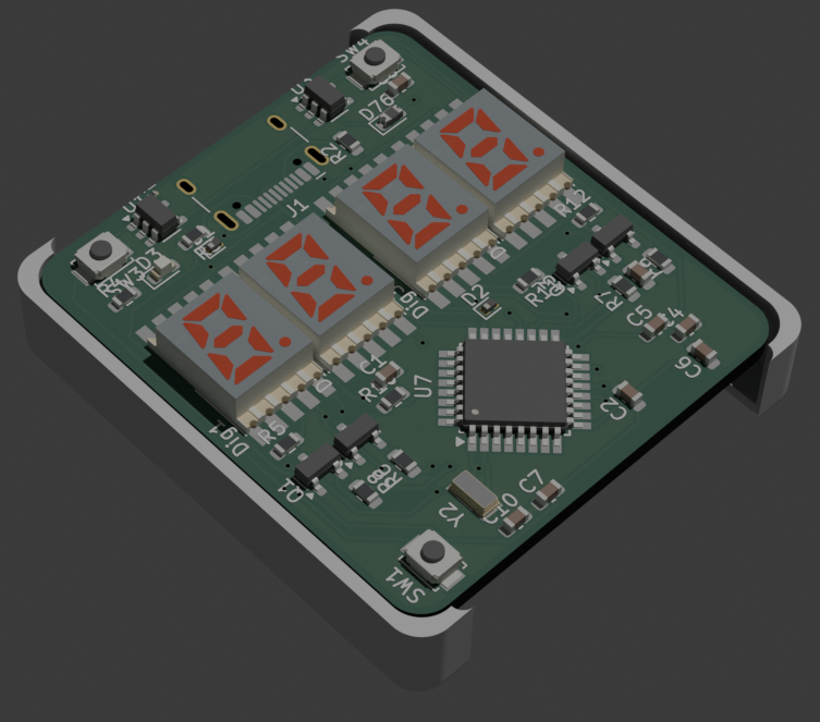
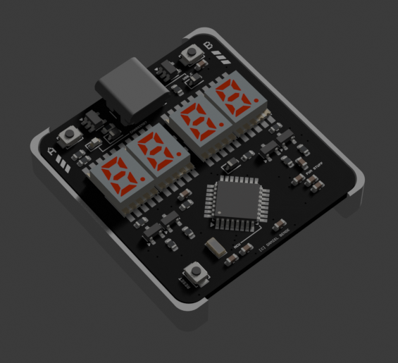
I also made a blender render of the current state:
(session duration: roughly 8 hours in total, maybe more)
Session 5
This is it now! I resolved a few routing issues and added test pads for burning the bootloader since the SAMD21 doesn't come with a USB compatible bootloader by default, and I've also added the 3d model for the case to the repo. The main thing I did in this session was creating a rough BOM which I've listed below:
| Item | Estimated price |
|---|---|
| PCB Assembly (JLCPCB) | $110 |
| J-Link clone (Aliexpress) | $10 |
| 2x Keystone 1060 coin cell holders (LCSC) | $9 |
| 2x LIR2032 coin cells (Aliexpress) | $5 |
The battery and holder are separate because I'll solder them manually to save on JLCPCB costs (double sided costs significantly more), and with that done the project is pretty much finished!
(session duration: ~1 hr)
Session 6
After a fairly long wait, I received the boards from JLCPCB and tested them. The battery charger worked great, but I found two pretty major errors that prevent the board from functioning as it should. The first is the voltage regulator; instead of being connected to Vin, the SEL pin was shorted to ground, meaning that the regulator defaulted to an output voltage of 1.8V on the main 3.3V power rail. This wouldn't be too much of an issue other than causing a low brightness on the displays; 1.8V is still within the operating range of the SAMD21. Because of this, I moved on to testing flashing a USB bootloader. After several hours of debugging with OpenOCD using various adapters, I came to the conclusion that something was causing the microcontroller to reset every ~0.1 seconds, rendering it impossible to flash any program to the board. This was confusing, so initially I tried shorting the debug pad for the RESET pin to the power rail to prevent it from doing this, but it didn't help. After this I decided to review the schematic to find the issue, and it was fairly obvious...
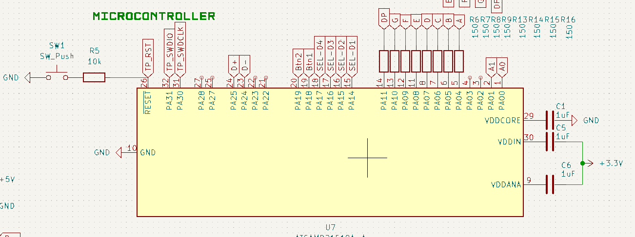 |
| Capacitors C5 and C6 should connect to ground, with VDDIN and VDDANA connected to 3.3V |
This prevented the MCU getting power, so constant brownout errors were occurring. Originally I was going to bridge caps C5 and C6 to direct power in, but these capacitors were almost essential when running on battery because without them the board would randomly reset and lose the time. I concluded that another production run with corrected schematic was necessary.
(session duration: ~5 hrs)
Session 7
I decided to remake the board in EasyEDA Pro pretty much from scratch. The schematic is the same as the previous version for all the working parts, but I also incorporated fixes for the regulator, power rail, reset button and input capacitors as well as adding a ton of test points just in case. The first stage was getting used to EasyEDA - it's much better than the last time I used it, but the keyboard shortcuts are completely different to KiCad's! After some adjusting I managed to get a complete schematic made, with fixed power input and a tweaked layout design.