Eink Watch
Day 1 (15th of March 2025)
Initial Goals
- Be completely phone independent
- Use a Eink display (with builtin circuitry)
- Be based around the RP2040 (Quite high power usage, but powerful and familiar) architecture
- Basic App Launcher
- FreeRTOS?
- Expose I2C, SPI and some GPIO (Space dependent)
Choosing an Eink Display
Step one, is choosing the eink display that will be used in the project. as this determines: - Physical Size - Physical Shape - Idle current - Display communication standard
It also needed some basic features - 2 colour panel (cheaper, easier to use) - Good software support by libraries like PicoGraphics and existing display drivers - A decent refresh rate - Small (like 1.5" small) and vertical
Looking at Waveshare's site, you get the following options:
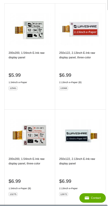
I went for the 200x200 1.54" 2 Colour board due to it being cheap and matching my requirements
Day 2 (16th of March 2025)
Choosing a battery
My requirements for a battery are quite simple:
- Be 3.7v
- Be physically small
- Be rechargeable
I decided on part 302530 due to it's size. It does not have free shipping however, as the one with fre shipping was significantly more expensive.
Other thoughts
- BMS board and main board may need to be seperate because of space. I shoud try to fit it all on one though
Starting the board design:
I started the design with the part I'm least familiar with (The Eink display interface). Basing my work on Waveshare's reference diagram (found in their datasheet on page 8.
Aand, this is what I ended up with schematic wise:
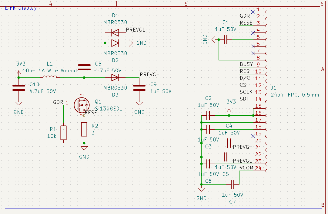
I intend to use 0805 or 0603 passives, since they are relatively easy to solder whilst still being small.
The next step was to assign footprints, and start layout. As mentioned above, most passives are 0805, but the inductor is 0604 and I had to go find a footprint for the FPC connector (AFC07-S24ECA-00).
And, then I hit a stumbing block, the display's mechanical drawing does not mention where the flex is in relation to the rest of the module, so idk where to place the fpc connector. I have opened a support ticket to ask for the measurements
Day 3 (18th of May 2025)
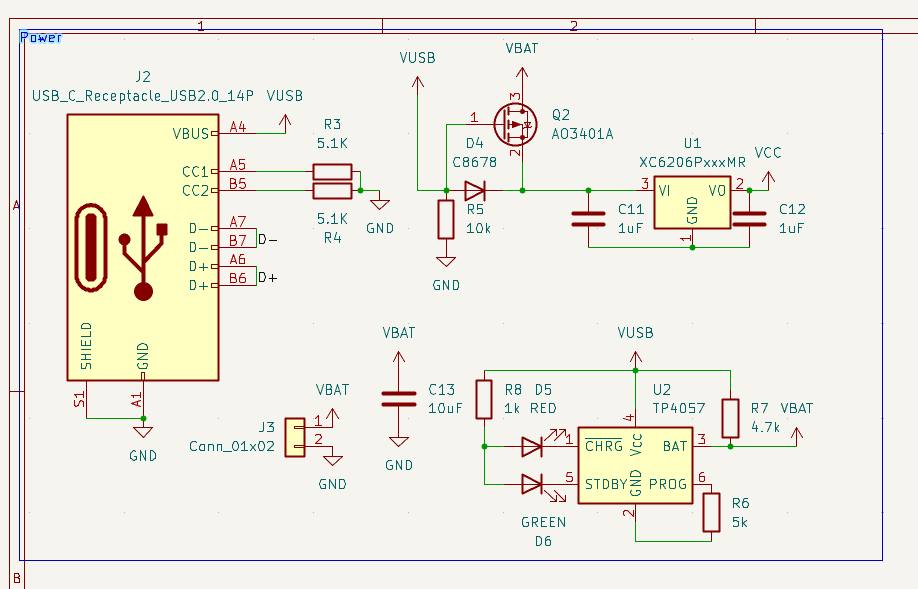
While I wait for waveshare to get back to me, I got started on the other components, Specifically the Power Management/Battery Management Systems.
Requirements:
- USB Battery charging
- Switchover between USB Power and Battery power (obviously)
- Be small, yet safe
Using the TP4057, I need a 5k resistor on PROG to configure it for a 200mA battery
Picking a voltage regulator
I need something that's cheap, 3.3v and small. I eventually settled on the XC6206P332MR due to it's wide voltage range for input. Howver, it does give more current than I need, which gives the device headroom for doing things like plugging in GPIO devices.
The actual circuitry
I decided to base my design around the circuitry used by Sparkletilt/Karmanyaahm, due to it being known good.
Aand, this is the quite messy schematic. done and dusted :)