
Lens Board
Mechanical keyboard with physical elements :)
Total time spent: 64.5 hours
Lens Board - Journal 1 - 15/05/2025
Lensboard is a keyboard! I did hackpad v1, but didn't get to do hackpad v2 due to exams :( Other than being a keyboard, Lensboard has some unique features...
Introducing...
ANALOG INPUTS! Physical controls are the single most satisfying thing in the world. Clicky, scrolly, wavy, whatever - as long as it's physical, it's fun.
The Plan
Quick overview:
- 1800 Compact Layout (Fullsize but squished)
- Low profile
- White backlight
- RGB underglow
- Audio Visualizer (physical)
- Scrolly Wheel (clicky)
- Fader
- Mini touchscreen (for color pickers, music player)
Audio Visualizer
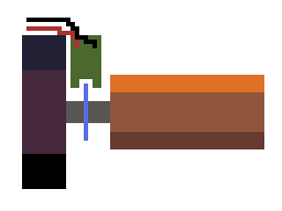
Basically, this is a line of little rods, that move up and down based on a fft of the audio input. They're moved by ten litte stepper motors (because servos are noisy as hell).
Here is my amazing diagram:

And these little green bars will move up and down with audio.
Scrolly Wheel
Its a scrolly wheel!
Apologies for my absolutely atrocious drawing skills, but here is what I'm thinking for the profile.

This will likely be 3d printed, and use a rotary encode so its nice and clicky.
Fader
I'm a bit of a lighting nerd, and as you know, lighting nerds love faders.

This is just a user mappable fader, but I'll probably set it up as a lighting thing, so I can move it and have stuff happen with lights in my room lol.
Mini Touchscreen
I just like the idea of having a tiny little display in the corner.
It'll probably have a little media control center or color picker for art stuff or lighting programming.

Welp...
Thats me for today! I'm gonna start some research on parts for tomorrow's entry, but thats my overall vision for this project. Looking forward to getting this going!
Time spent: 2 hours
Lens Board - Journal 2 - 17/05/2025
Today I'm just doing some more thinking on some specifics of the parts I'll be using for the analog input on the keyboard. I'm just going over all the parts (touchscreen, wheel, faders, etc.) and figuring out how they'll be actually integrated into the board.
So, without further ado:
Touchscreen
I'm just going to go with a generic TFT touchscreen for this. I'm decided between 1.8, 2.2
, or 2.8"
If I go 1.8, then I have less of a problem with it fitting on the keyboard, but 2.2
seems to be the most common size (and has some pretty decent resolutions for cheap).
Scrolly Wheel
As I see it, I have two or three major options for the scrolly wheel.
Option 1 - Rotary Encoder
Basically, mount a rotary encoder horizontally, attach the wheel, and its done.
This approach is nice and easy, but also might have some problems.

When the user presses down on the opposite side of the wheel to the encoder, there might be some flex, and there could also be some problems with the encoder legs bending, which might be very annoying.
Option 2 - Motor with Encoder
Option 2 is just a DC motor with a magnetic encoder.
By doing this, you can have the microcontroller be aware of the wheel position as with a rotary encoder, but you can also move the motor to simulate the detents of a regular rotary encoder. You can also program it to have different motion profiles, like maybe a snap back to the center after moving.
Unfortunately, this approach has about all the cons you could think of: - More expensive - More physically complicated - Harder to implement - Bulkier - Still doesn't solve the bending problem
Ultimately, I'm probably going to go with the rotary encoder, mainly because of space, but I need to find a way to hide the actual encoder and support the other end, maybe this kind of system:
But I also want the wheel to be above the case, so more thought is required.
Faders
I think maybe two faders would be better, just looking at the layout of the touchscreen, scrolly wheel, and faders.
Heres my beautiful mockup of how it might look. This section will sit to the right of the keyboard and there are two main layouts I'm considering.


Honestly, I don't mind all of these (ignoring the ugly colours lol), but I think either the first or third will be what I go with. It doesn't make too big of a difference to the electronics which I do, so for now I'll just design as if I'm doing the first one.
As for the actual faders, they'll probably be around 60-80mm of travel, and other than that, just generic faders.
Audio Visualiser
Alright, the big, annoying, how the hell will I do this
part!
Well, I've had a bit of look and I've come up with a bit of a plan.
First of all, choosing the motors.
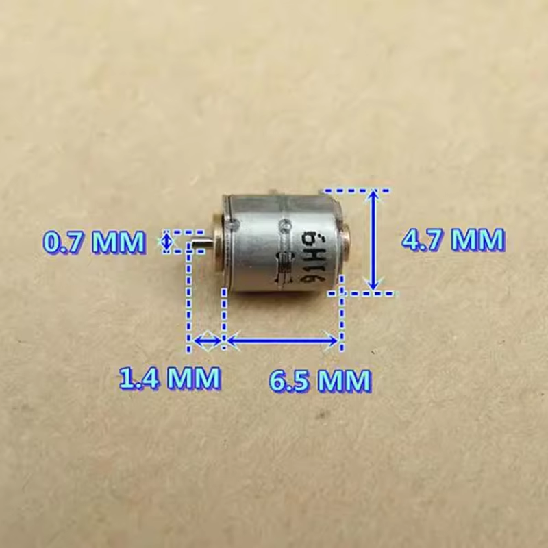
Aliexpress has once again come to the rescue, with some tiny steppers intended to be used in camera lenses, but will work perfectly fine for my use case. These are absolutely tiny motors, but they are fully dimensioned, which is an amazing attribute to have.
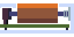
Now onto the actual mechanism for driving a pin. I'm going to use a basic cam follower mechanism, which not only ensures smooth transitions between positions, but is also probably the easiest method to build, having no gears which are hellish to 3d print.
By controlling the rotation of the cam (because they're going to be steppers, not DC motors), you can control the height of the pin.
Quick sidenote, but the cam profile could technically be better utilized than the above diagram in order to maximise the distance resolution per degree, if it were similar to the following profile:

But this also limits the cam to moving in one direction, and adds a sudden drop when looping, so a pear shaped cam is better for my requirements.
Das ist alles, tomorrow I'll get started on the actual schematic design.
Time spent: 2 hours
Lens Board - Journal 3 - 20/05/2025 - 21/05/2025
*Note*
Forgot to write this but I changed to metal gear servos
because stepper motor drivers were too bulky / expensive
Actual schematic design is taking place!
First of all, picking an mcu.
This is mainly determined by the number of pins required, which is as below.
For the audio visualizer, actually going to go with steppers, but some slightly nicer non plastic geared ones and have them running slowly so they don't make as much noise.
Pins:
- <25 - Key Matrix
- 2 - Rotary Encoder (scrolly wheel)
- 1-2 - Faders
- 5-11 - Regular Screen / Touchscreen
- 10 - Audio Visualizer (1 per servo)
- 1 - Neopixels Overall - <51 pins
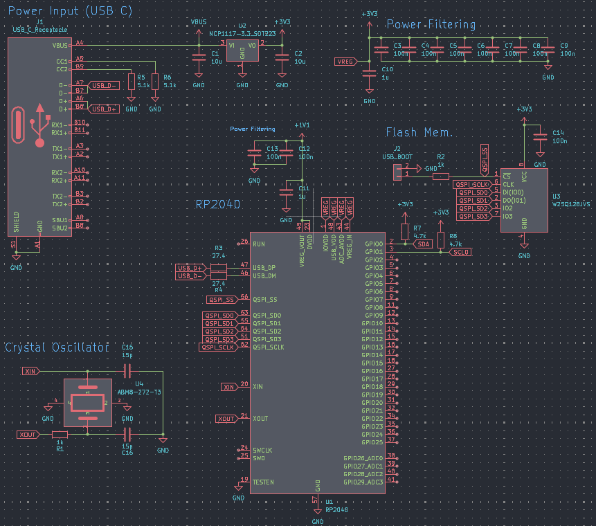
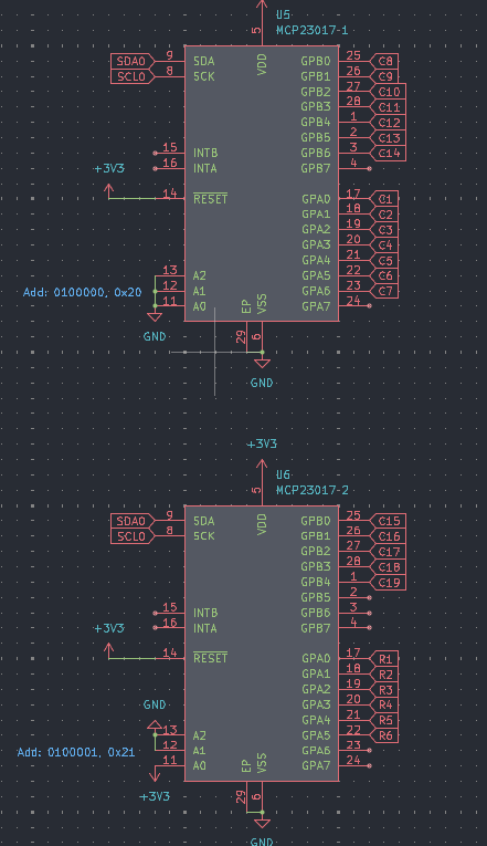
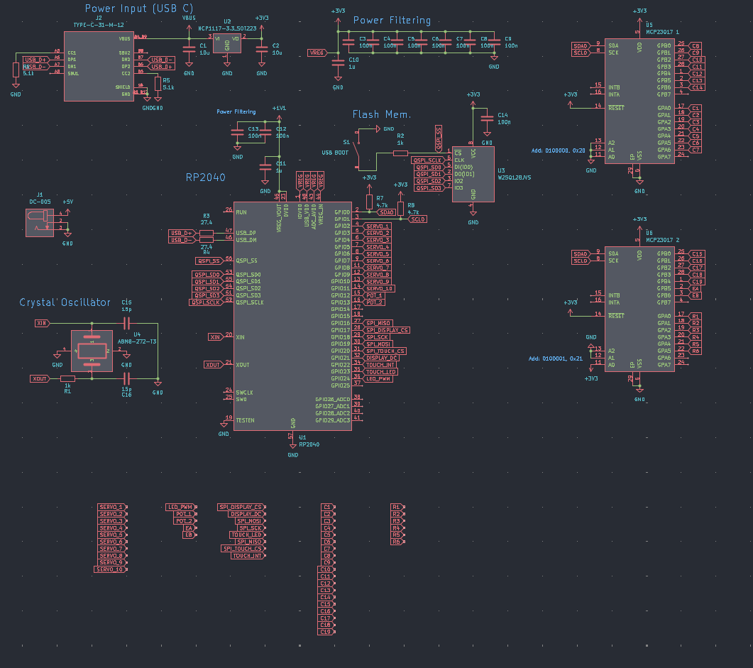
To this end, I've decided to go with the rp2040, which has 25 gpios, and use 2 mcp23017s to get it up to 57 total pins. I've used the rp2040 before on another little macropad, and its got really good design documents and spec sheets, so it should be easy enough to get it working and running qmk.
I've already made a board using the rp2040 in the past, so I can luckily just copy the schematic over for the base design, and just add the key matrix, io expanders, and other stuff on top.
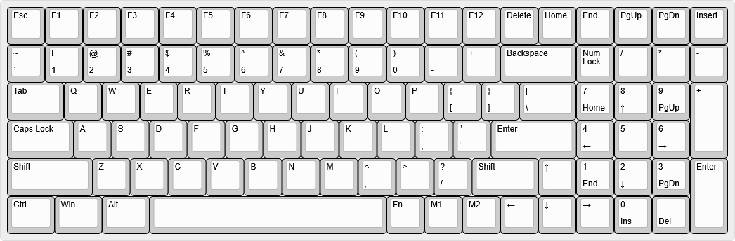
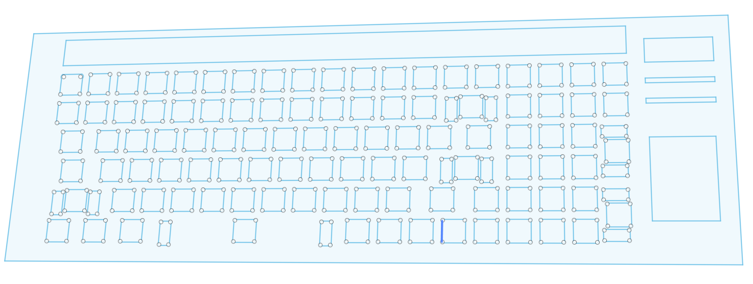
The keyboard layout
As I've already said, this is going to be an 1800's compact layout, which is basically a fullsize keyboard but a bit squished.
1800's layouts typically have only a few of the navigation keys (home, end, pgup, pgdn, del, ins), but I've decided to include all of them, at the expense of a few utility keys (menu, prtsc, right ctrl, right alt, right win). I also have included two macro keys (m1 and m2) which will probably be just user defined.
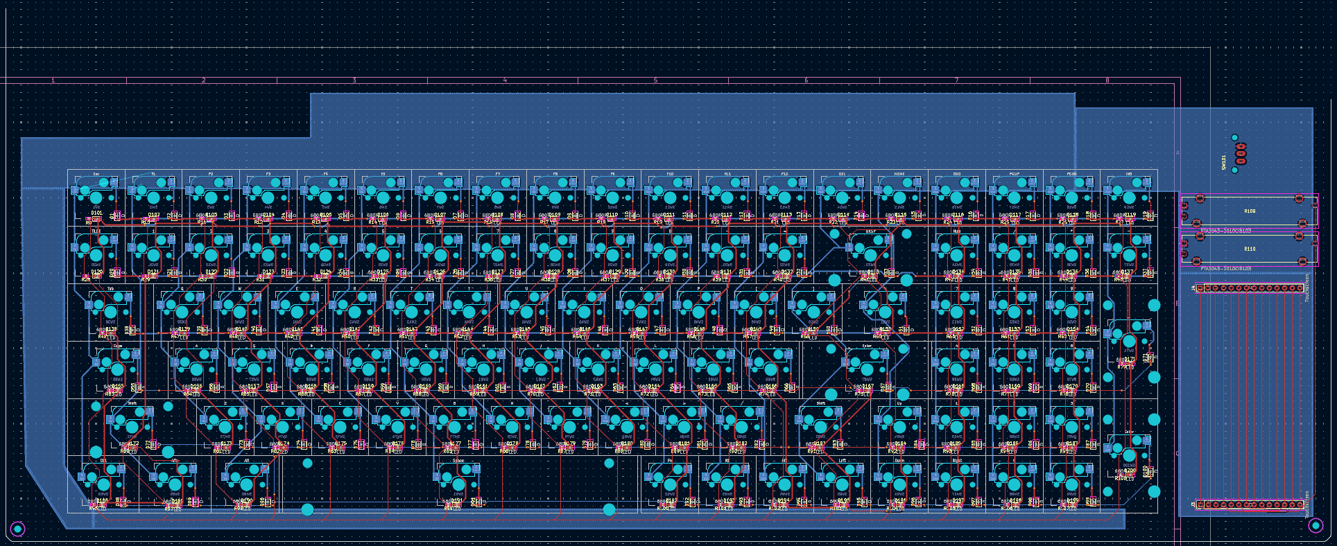
The schematic:
After several hours of work, I've got the basic schematic done for the key matrix with the io expanders. I used a 19x6 matrix, which isn't the most efficient, but it makes routing and layout a lot easier than a 10x10 matrix, and doesn't take up too many extra pins (only 5 more than a 10x10 matrix).
Key Matrix

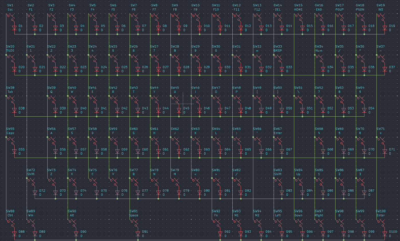
Microcontroller
IO Expanders
GPA7 and GPB7 cannot be used as inputs
Alright, thats all for today, continuing with the schematic tomorrow to finish up with the other components. Touchscreen is the only one I'm mildly concerned about, but it should be fine.
Time spent: 5 hours
Lens Board - Journal 4 - 22/05/2025 - 28/05/2025
My deepest apologies review team, I have not been doing much journalling for the last week or so, because i've only been able to work on this project in mini chunks at school, etc, and haven't really had time to properly write anything.
Regardless, the last 6 days have been dedicated to finalizing the schematic and laying out the pcb, both of which are now done!
I'll try to go over everything roughly in chronological order, but y'know, some things might be skipped over or improperly ordered.
Schematicizing!
I finished the schematic on the 24th, and it wasn't too bad. I just chucked on the touchscreen, using a generic spi interface with touch also using spi, and then added in the faders and scrolly wheel. Faders are super simple, just a potentiometer effectively, and the scrolly wheel is just a rotary encoder.
Time spent: 1.5 hours
PCBinizing!
Alright, this one was a bit of a rocky road, but its pretty much done now...
Part 1. The Basics
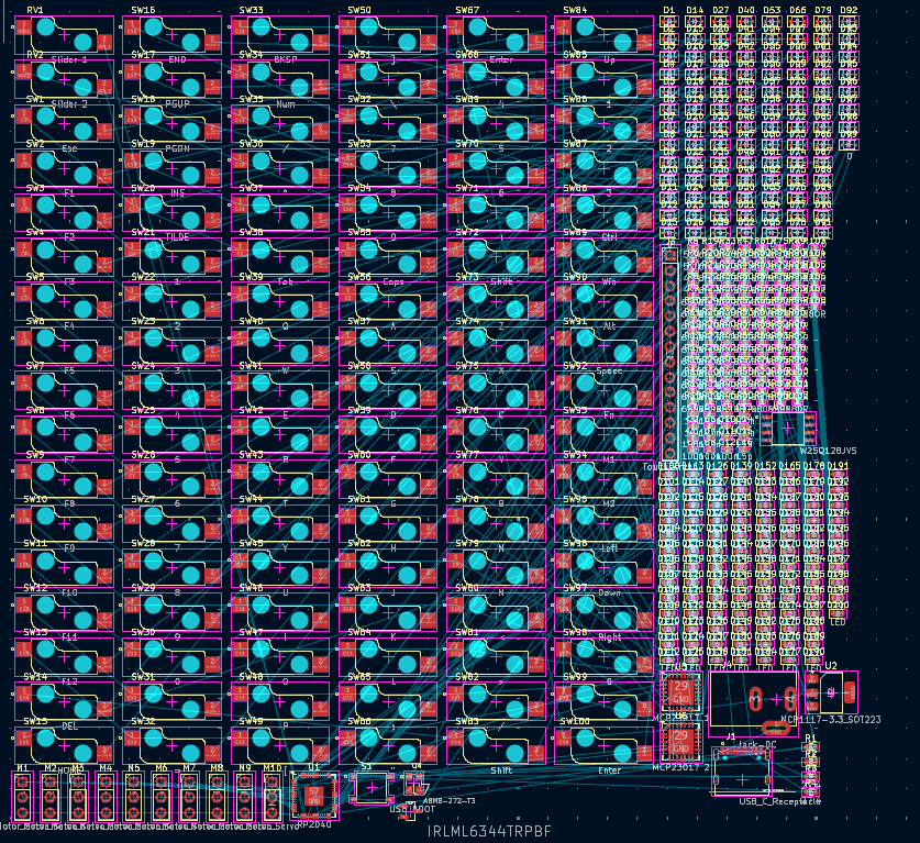
The first part of the pcb I did was just laying out the actual keyswitches, because they've got a predefined layout which makes it super easy to just place them without worrying about routing and stuff. I decided to use Kailh hotswao sockets, because they're pretty cheap on aliexpress and seemed more reliable and easier to desolder than millmaxes.
I started by just dropping in all the footprints, and laying them out with the correct spacing. Spoiler alert, this was completely wrong, and I only realised this after I had done all the routing and everything... Next I chucked in the diodes, LEDs, and resistors, which was decently easy but took literal hours because each of the 300 components had to be placed effectively by hand and then routed.
Regardless, at the time I thought it was fine, so I continued on with the basic layout, now the start of the microcontroller section.
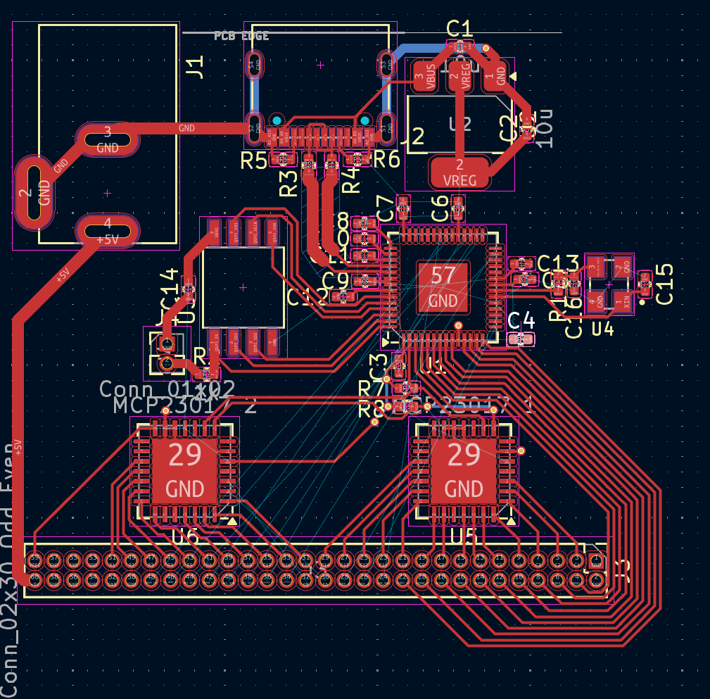
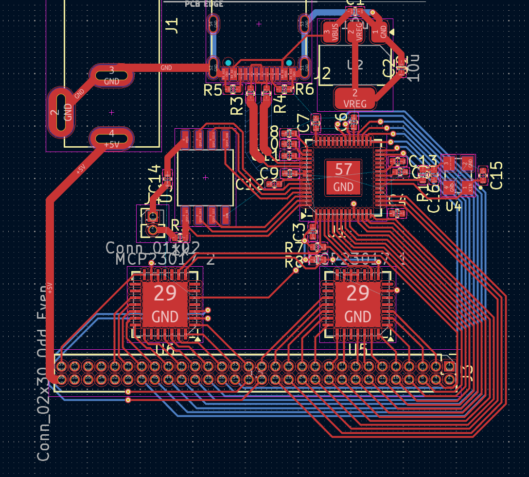
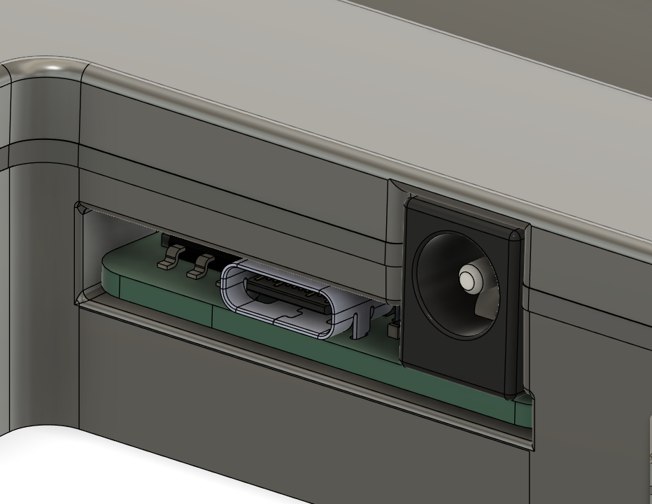
I started by hunting JLCPCB parts for a couple suitable connectors, and miraculously found some that had readily available footprints online, so the usb c and dc barrel jack were both easy to sort out. The placement of the rp2040 relative to the connectors was pretty important to get right, so i spent some time making sure I wouldn't have any grounding, impedance or stupid usb issues.
After laying out the microcontroller section, I started routing it, starting with the usb D+ and D- lines, then the power lines (placing the decoupling caps as close as possible), and then the crystal and other random stuff.
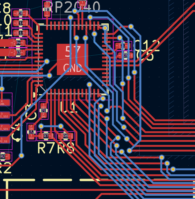
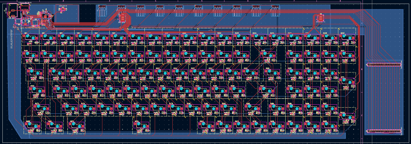
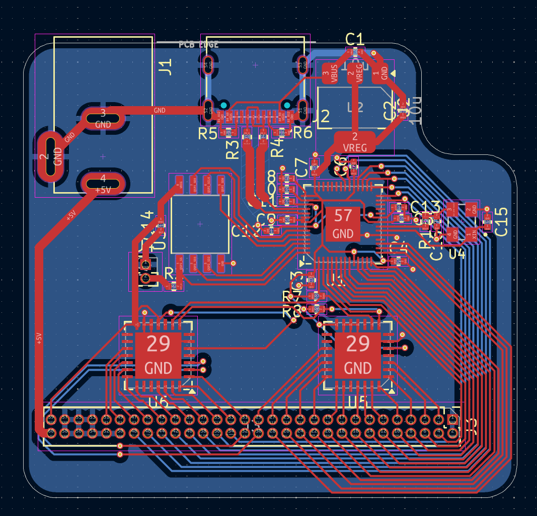
Next up was the io expanders, which were just chucked on either end of the board, and then quickly routed. If you look at the actual routing, you might notice I have a lot of parallel traces, which is a bit iffy, but hopefully it'll be fine, because there's a ground plane and they're not too long or close.
Getting the traces down to the actual key matrix was a pain, because there's 25 traces which have to cross the i2c lines, and in the end i kinda just gave up. There's a lot of vias, and a lot of bad practices, but I think it should be ok.
Time Spent: 13 hours
Part 2. My amazing design skills
Just yesterday, I searched up how kailh hotswap sockets actually work, and realised that I had placed them completely wrong. Not only were they on the wrong side of the board, but there were also no holes for the actual keyswitch poles to go through, so I kinda had to reroute the entire keymatrix and leds. This was a massive pain, and as of the time of writing this, I'm still fixing traces which now pass through holes in the board :(
Anyway, once that was all fixed, my board was finally nearly done-ish, just needed to add the faders, scrolly wheel, and audio visualizer, as well as mounting holes and other random stuff.
Time Spent: 4 hours
Total Time Spent: 18.5 hours
All right, images and more details will be added to this journal later, but for now, hopefully this is enough to sate your eternal hunger.
Lens Board - Journal 5 - 29/05/2025 - 30/05/2025
Alrighty!
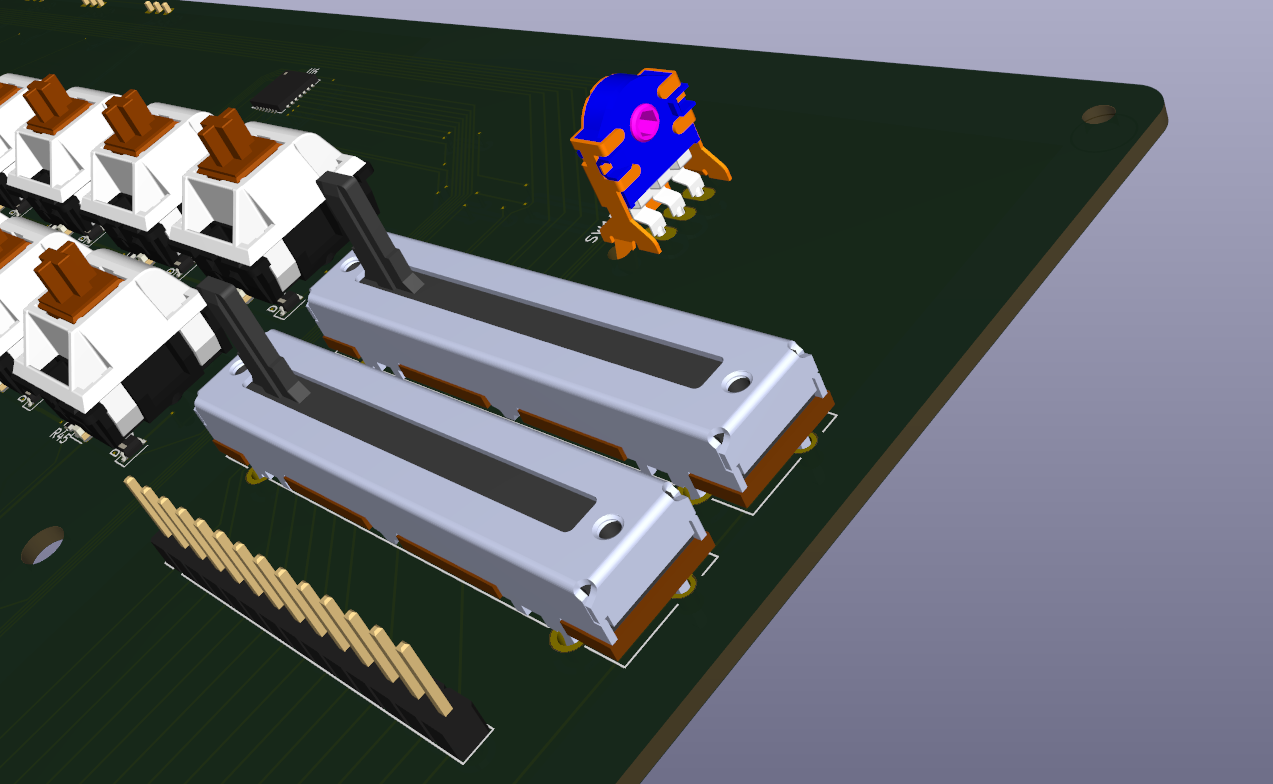
The past couple days have just been spent adding some finishing touches to the pcb, rerouting the keymatrix, tidying up some routing for the io expanders, and finding footprints and routing the faders, scrolly wheel, and servos.
Somehow I managed to find an actual footprint for the sliders which is available on jlcpcb as a part, so that was amazing.
For servos, i'm just using a 3 pin header and I'll just hope that they all fit lol.
Scrolly wheel I yet again found a encoder that was exactly what I needed, available on JLCPCB, and had footprints readily available. I went with the AlpsAlpine EC11 something something, I've used other pots of theirs before on my macropad (which is sitting right in front of me atm actually :), and it has the right form factor for my wheel to work well.
I'm going to start working on the case now, so wish me luck! Fusion 360 is a hellscape for a blender person like me :(
Time Spent: 4 hours
Lens Board - Journal 6 - 31/05/2025
Hello again!
Today was focused on making up the plate for the keyboard and sorting out what I'm going to do roughly for the case.
The Plate
To start with, I did some research on plate materials, and decided on 1.5mm aluminium, which should be decently cheap on jlccnc, and also be just a decent overall material.
*UPDATE*
I have got a quote from jlcpcb for this,
and it ended up being around 50 bucks,
which should be within my budget.

Onwards!
I tried a couple methods for getting the plate, but eventually just used ai03's plate generator and editing the final thing. This took way longer than I thought it would because fusion 360 kept on moving my plate around instead of resizing it. At the moment, I have a slightly better understanding of how it works, but I ended up having to redo everything three or four times before getting it right. Not only this, but because I kinda just eyeballed my pcb, I had some awkward dimensions to work with, but I think its all good now!
Time Spent: 3 hours
Lens Board - Journal 7 - 01/06/2025
So...
Fusion 360 failures strike again! I accidentally resized the plate to 10mm too big, so I had to redo a bunch of dimensioning rather than actually work on the case, and now I'm going to go to bed. Sorry for short journal, had final dress rehearsal tonight and am ubermüde rn.
Time Spent: 2.5 hours
Lens Board - Journal 8 - 2/06/2025 - 09/06/2025
Again, super sorry for the lack of updates, this is mainly because I've had no time to work on this at all due to show dates for school production, so i only could work on it during school lol, but over the past day or so I've had some time to work on the case for the keyboard, and I've managed to get it to a point where it could almost technically be functional.
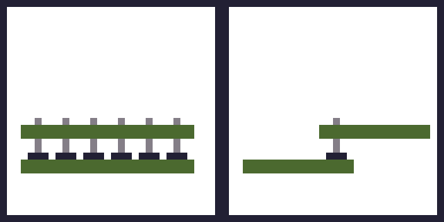
At its current point, I'm using a sandwich style mount, where there's a bottom case, plate, and then a top case. The pcb could technically just be supported by the plate, but I'm going to use some standoffs just because the keyswitches aren't soldered, and it should also help the sound a bit.
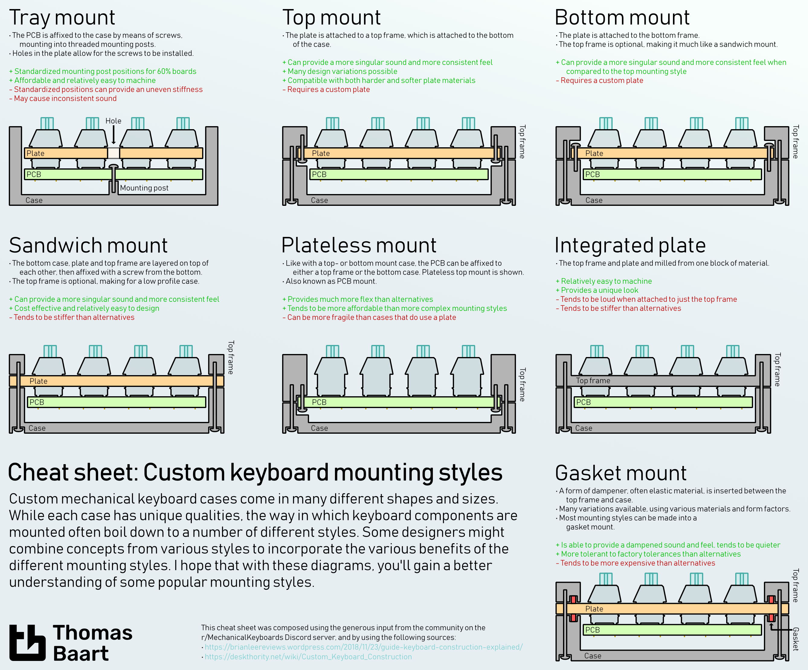 Source: Thomas Baart
The main reason this took so long is because everything I do is actively fought against by the software, but it's looking fine-ish now so I'm happy.
More images coming soon, I have to go back through fusions version history bc I forgot to take screenshots and it takes a while.
Time Spent: 7 hours
Lens Board - Journal 9 - 10/06/2025
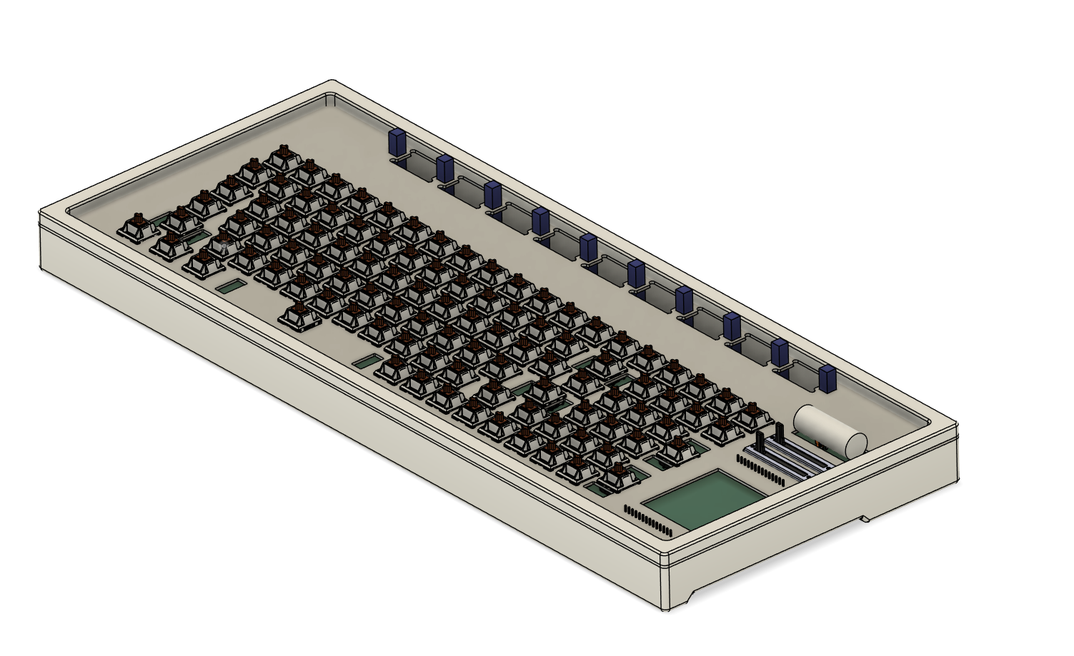
Today I did a bunch more work on the case, namely, adding screw holes, moving everything into their own components, adding the servos and their brackets, adding supports for the music visualizer pins, and fixing the plate (again...)
Screw Holes
As I'm using a sandwich style mount, I needed to have the screws go up through the bottom case (threaded) through the plate (unthreaded) and into the top case (also threaded), so that the top case pulls tight the plate.
I'm using some m2 threaded inserts, and I think I've got the right dimensions, but Aliexpress datasheets are confusing so y'know.
There are a total of 14 screws, 12 on the top and bottom edge, and an extra two in the middle. Hopefully this is enough to stick it together :)
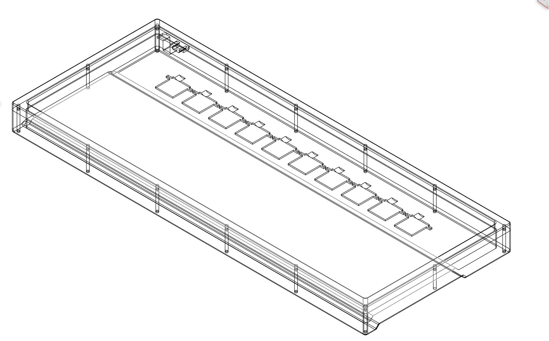
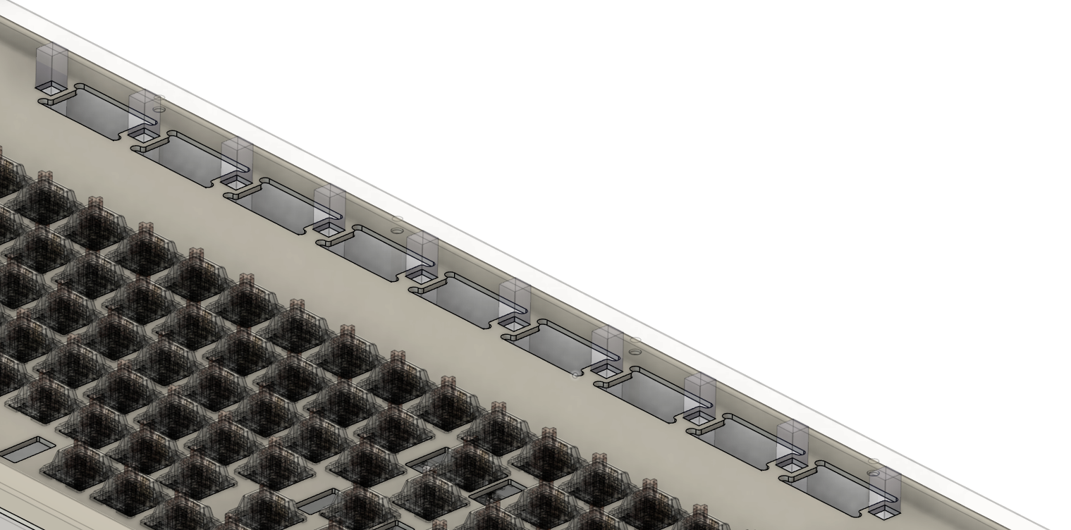
Servos
Not much to say here, I found a 3d model, added 10 in a line, and adapted the cutout in the plate to make it a bit prettier.
I'm pretty proud of the parts I made on the plate, as it was the first time I could actually get fusion to properly work how I wanted it. They're to support the pins and hopefully keep them vertical, although as I'm writing this I can forsee some issues with only one support section.
*Saving this for later, ignore please* link m2 od 3.2 l 3mm
Time Spent: 2 hours
Lens Board - Journal 10 - 11/06/2025
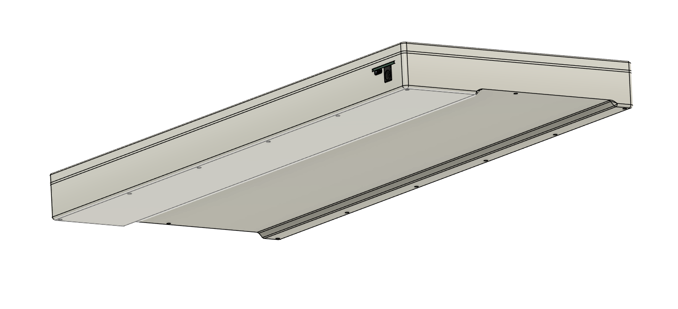
I'm just going to call it done now. I added a little chamfer ish bit to the bottom to make it more than just a flat case. It looks massively thick in the photos but in reality it's only very thick (only 5mm thicker than my current keyboard)
Also worked on checking prices for production, not looking great :(
Time Spent: 2 hours
Lens Board - Journal 11 - 13/06/2025
Hello! I've spent the last two days tidying up everything, reorganising, writing boms, and writing an actual readme instead of the journal. You can probably look at git if you want to see the major changes, but it's just generally making sure I meet the submission requirements.
Just now I've spent the last couple of hours rendering my keyboard.
I tried to do it in Fusion but gave up and just exported it to blender for rendering, and I must say, I think it looks pretty good.
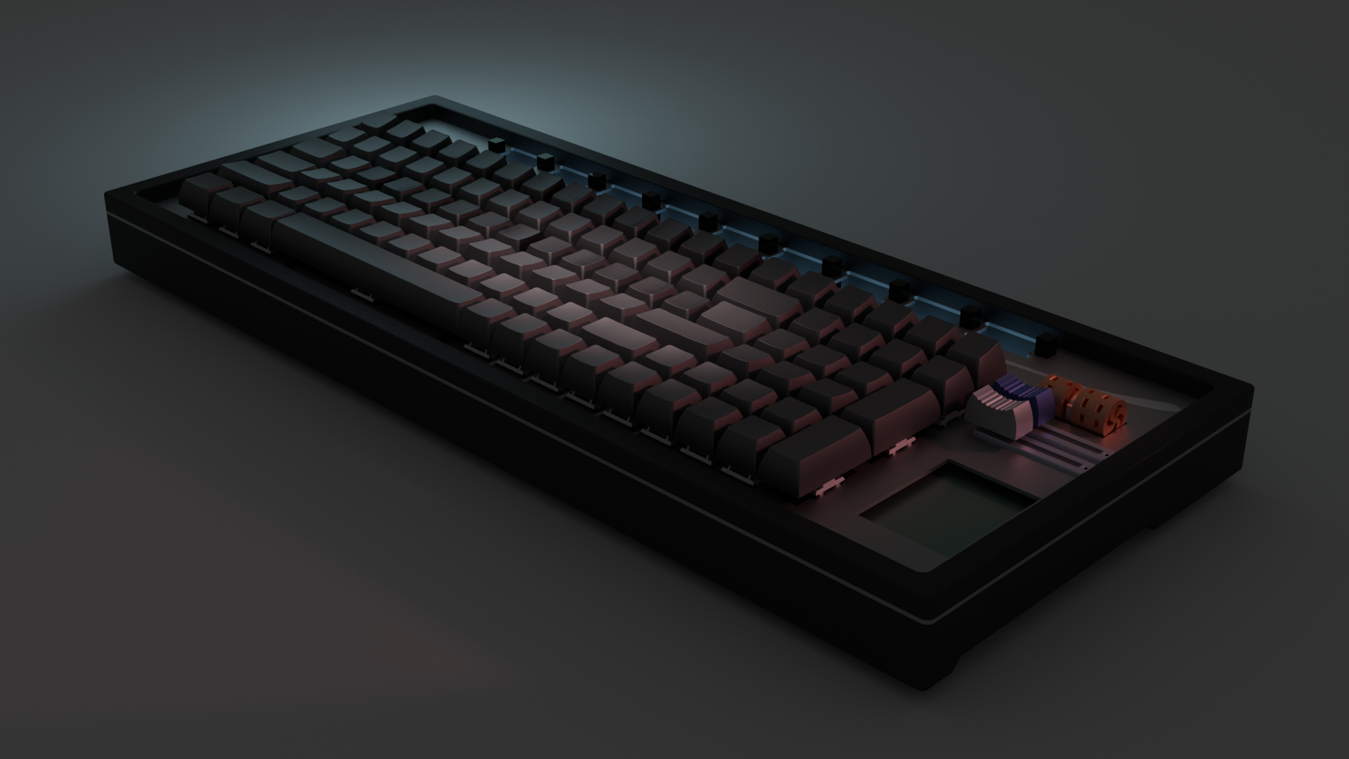
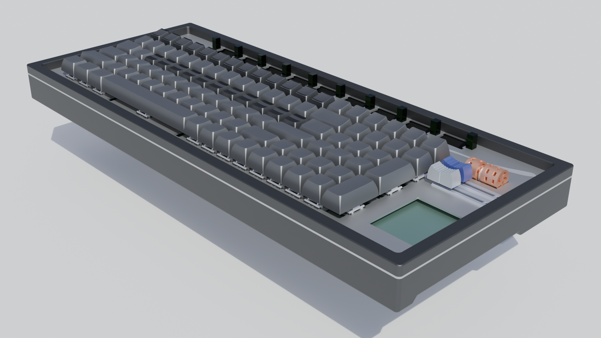
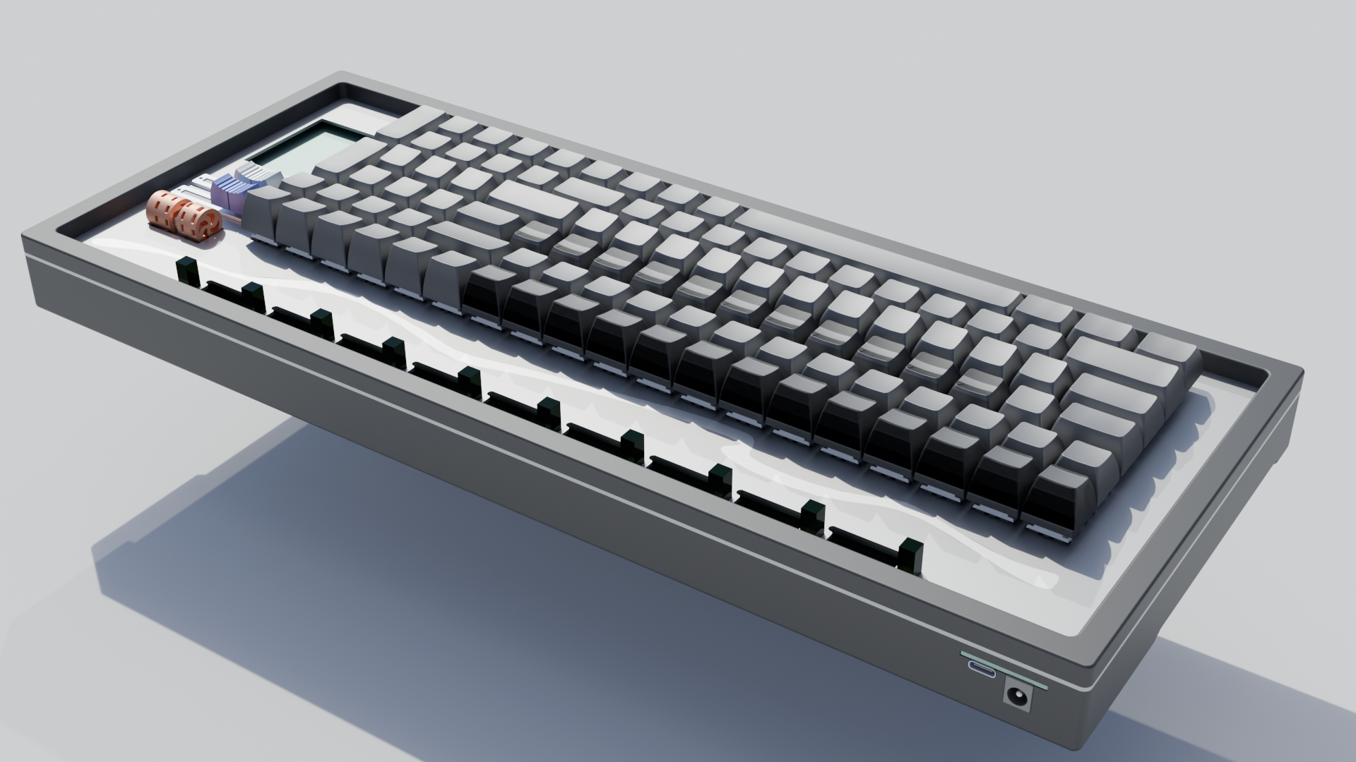
Literally submitting it as I speak, wish me luck :)
Time Spent: 4.5 hours
Lens Board - Journal 12 - 20/06/2025
Alrighty, I'm back for one last journal before fabrication. Today I'm going to try and cut the cost down significantly, as the total cost of the project is currently a bit insane.
First thing to try: Reduce board size.
Because of my weirdly shaped board:
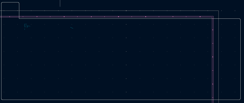 The price of the pcb will likely go up, just because the milling process requires more materials for oddly shaped, non tesselating boards. If I split the top section into a seperate board, then I can potentially reduce costs significantly.
Looking at JLCPCB's quoting service, my current board costs $45.30, through some quick calculations, If i split the board into two, it would cost a total of... $34.80, for a total savings of $10.50. Well. Not exactly the savings I was hoping for...
Checking the BOM again, I think the pcba is almost certainly the cause of this cost (~$100), so if I can bypass this it would save me a lot of money.
Technique 1 : Only pcba smd parts
I'm thinking if I only use pcba for the rp2040 and other chips that are impossible to hand solder, it should cut costs down significantly.
Just gone through the quoting process, and it turns out that this isn't actually much of a cost saver. it did lower it from $100 to $90, but $55 is just the large board fee. I'm now going to try doing the same thing for the smaller board, and see if the large board fee still applies.
Ouch. Still there, so need to try another method.
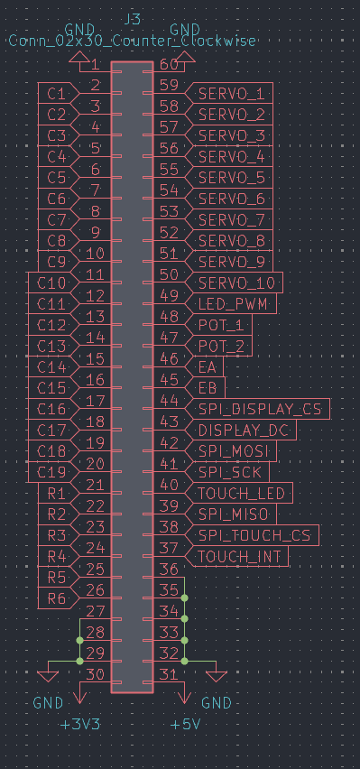
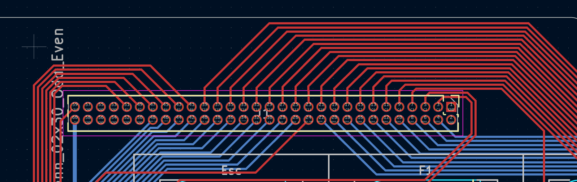
What if I put the rp2040, io expanders, crystal, and all the other hellish components on a daughter board with the connectors? This might not be great because then I have like 30 or so wires I need to cross over from one board to the other, but I do have a potential idea.
If I overlap the two boards, and have some pin headers extending upwards and connecting them, not only do I get a good and easy connection, but its also very cheap.
I'm going to do a test run of this, which might be a bit painful, as it requires rerouting the entire pcb, but I can forsee major cost savings.
EPIC MONTAGE!
Need 50 pins, jeepers
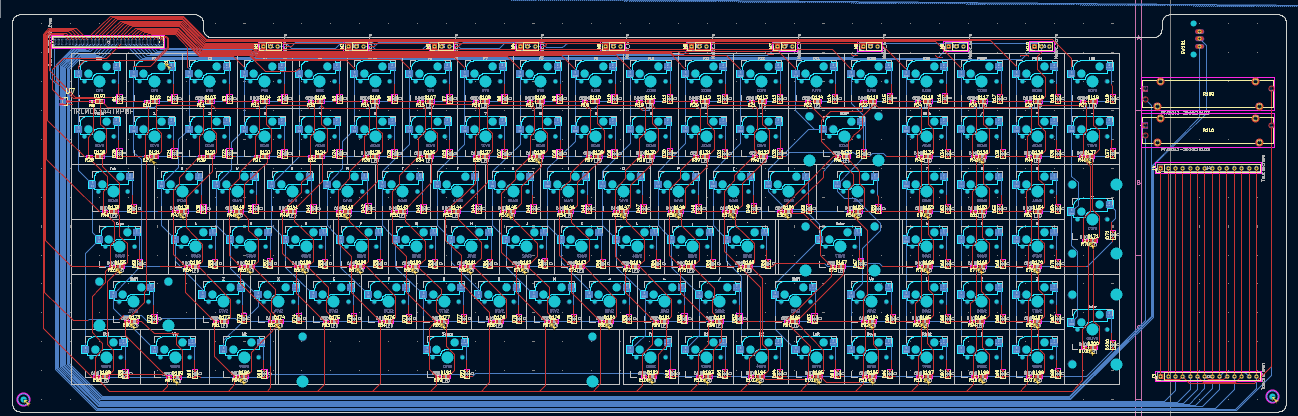
Alrighty! I've split the board, now its time to see if I actually saved any money...
The daughter board, including pcba, costs a grand total of \$21.96 a piece, or for the minimum order size, \$46.17.
The main board costs a total of \$5.38 a piece, or \$26.90 for the minimum order.
This gives a grand total of around \$27.34 per board or \$73.07 for the minimum order, including only the jlcpcb elements of course. But overall, this is a massive improvement compared to the previous cost of \$147.87. That is, of course, if you don't mind hand soldering 300 smd components...
Super happy with this, but now I've got a few boms to rewrite, so I'll update this again in half an hour.
Boms rewritten! Spoiler alert, it didn't take half an hour, but I do now have the total cost for the whole project.
The minimum cost (excl shipping, per unit price) is \$114. Minimum cost considering minimum order quantities is \$160.13, and the cost of a minimum order with shipping is \$168.94. For those interested, you can find the BOMs here.
I've slightly begun work on the case, but I'm going to do some work on other stuff today and finish it tomorrow, and then that will be the keyboard done (for the second time).
Time Spent: 8 hours
Lens Board - Journal 13 - 24/06/2025
Hello again!
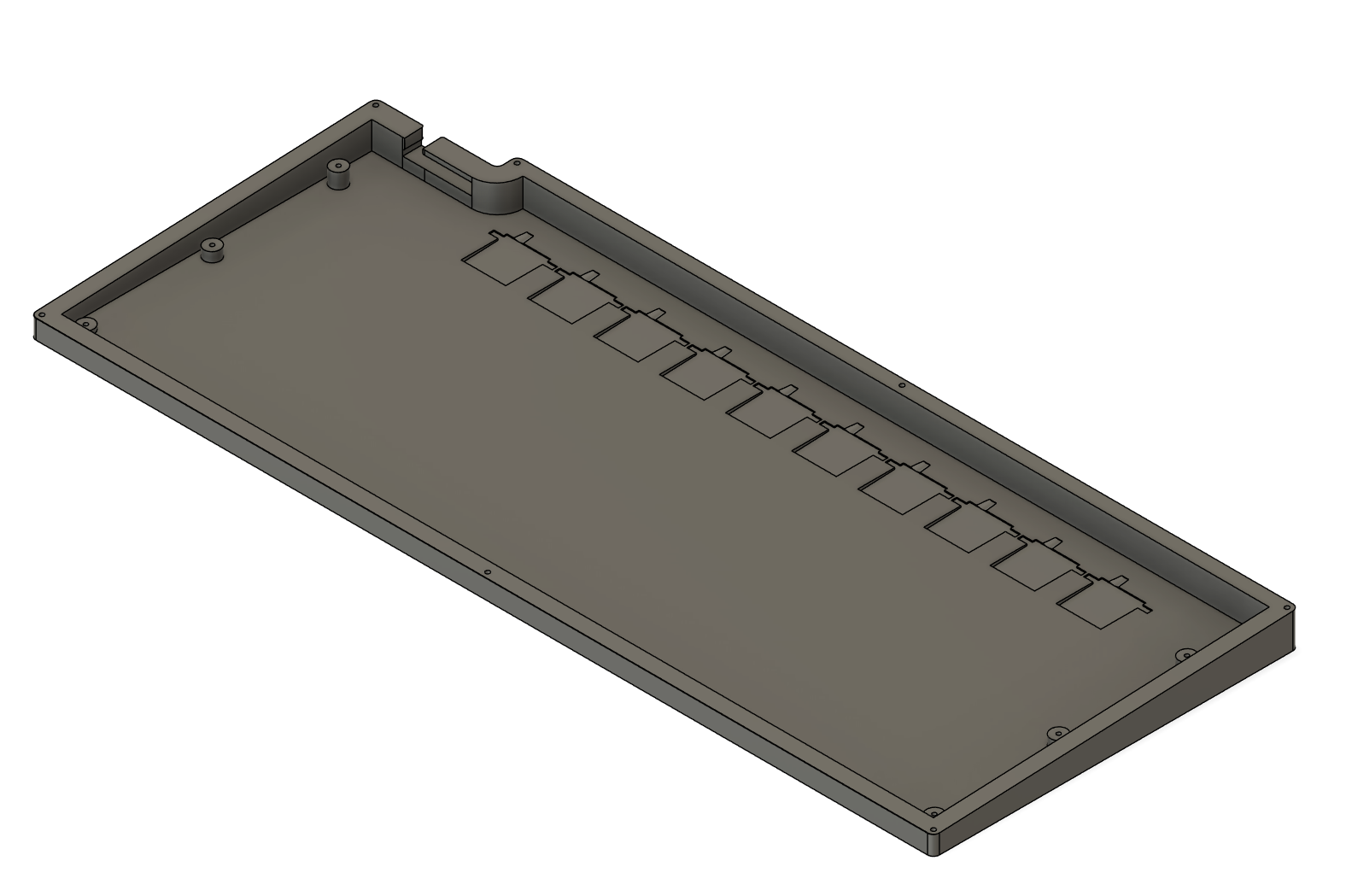
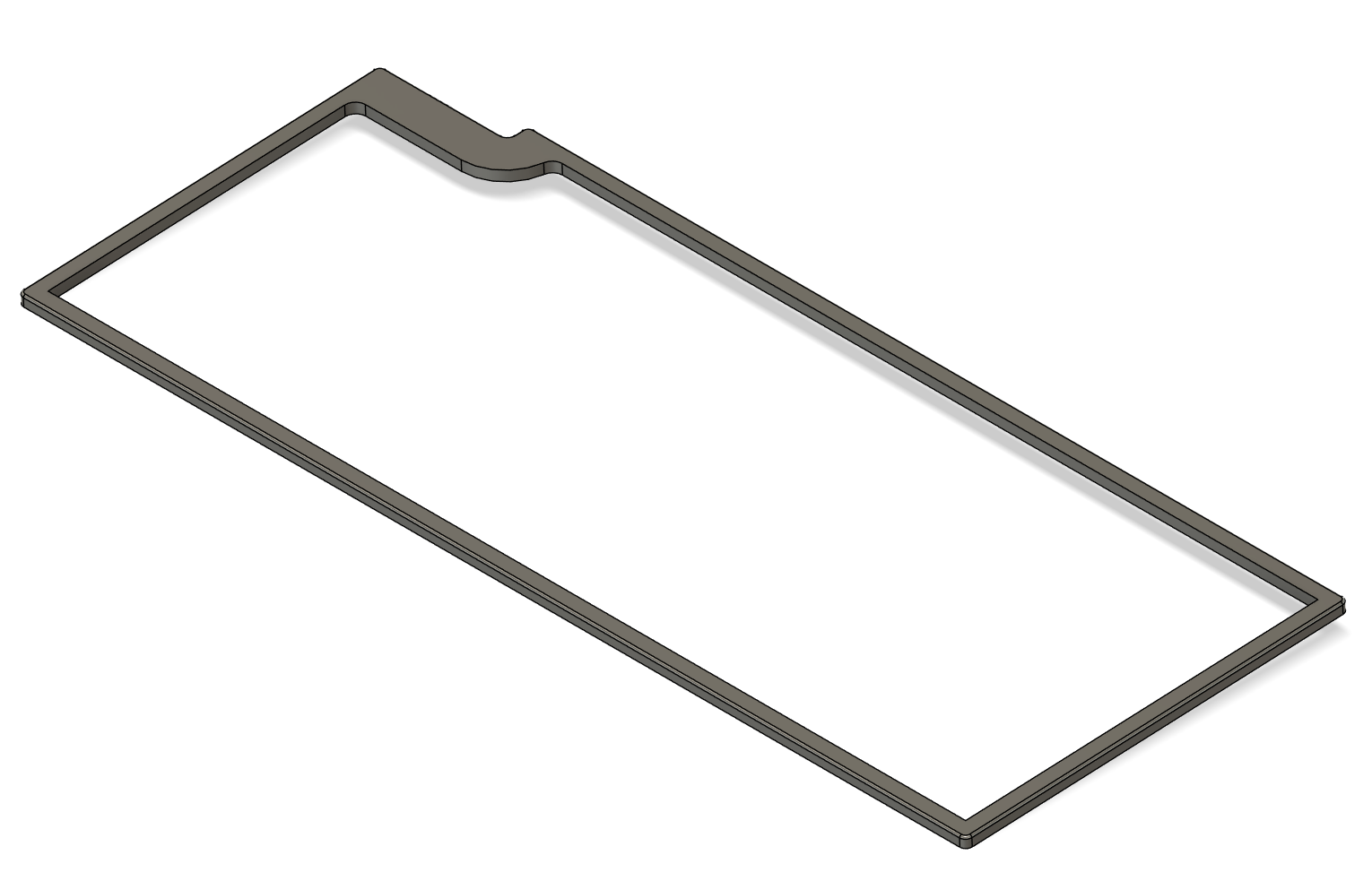
I've spent the last four days swapping between my other ongoing project and this one, and I've just managed to finally finish up the case design.
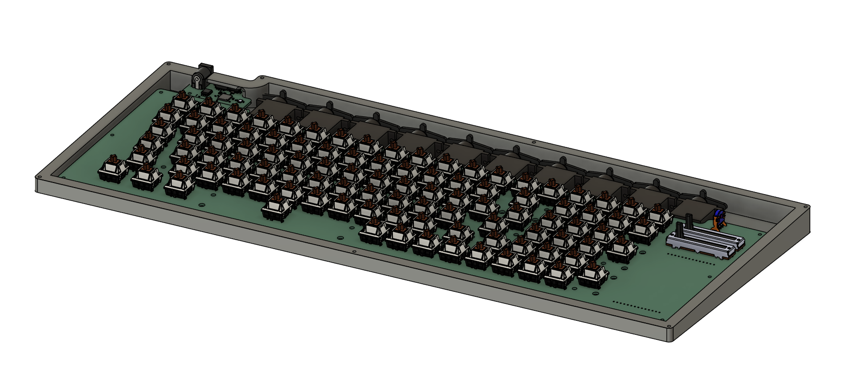
As it stands, it's made of three pieces, roughly the same as the last design. However, this time its way thinner, as I've angled the the top at 2.5 degrees which means at the top of the keyboard, theres room for the servos, while at the bottom, theres not a ton of extra space underneath.
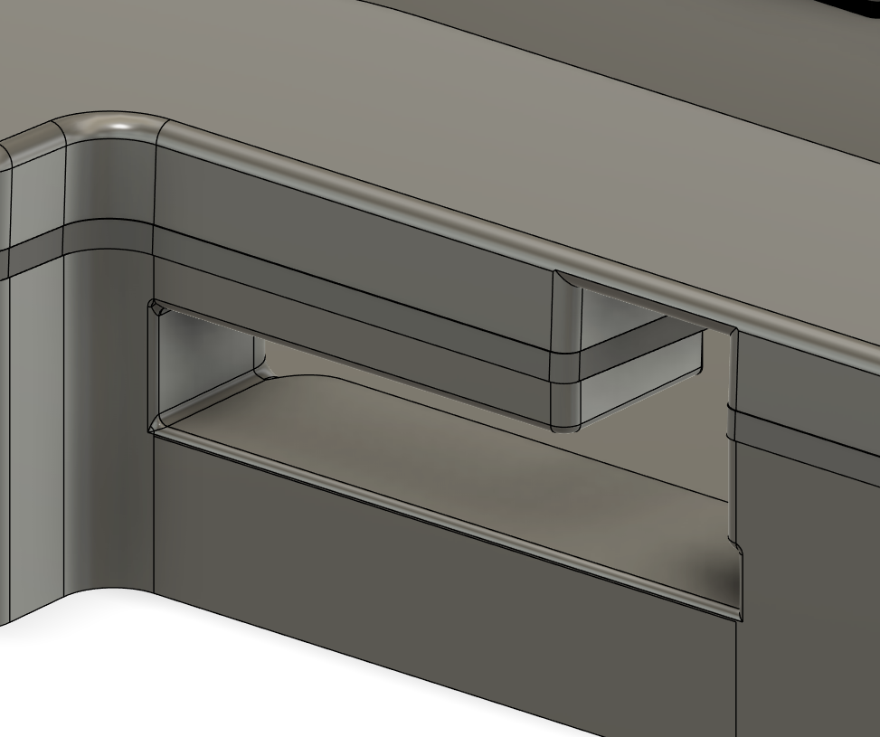
The seperation of the pcbs also helped, as I was able to add a little cutout in the mainboard which the servos nicely fit in to.

Time Spent: 6 hours