
Videography Light
A DIY Film Light for Videography!
Total time spent: 66hrs
July 8th
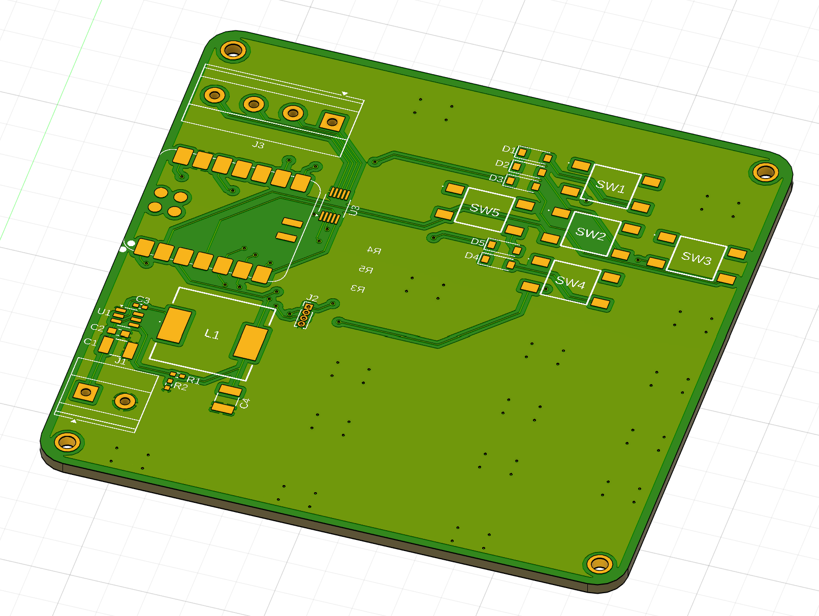
Final preparations for submission! Did some silkscreening for the control PCB, made a quick flowchart for the wiring, finished up the BOM, rendered out some nice images for the README, and well, wrote the README all in time for a note-so-late night submission (woah not 1AM really?).
Time spent: 7hrs
July 7th - @Jayx2u
With the PCB design completed, it was time for the case. I had the incredibly innovative never-seen before idea of placing a cube (with round corners of course) around all the electronics and calling it a day. Shocking and genius idea I know right, no need to thank me. ;)
 Annnnnd volia! A cube around the whole thing. Has ample space for all the components and the heatsink. The translucent component is the shell and the rest is the base. Printed in to different parts.
Then it hits me 🤸🏌️. How do I attach the base to the shell??? So voila again, version 2, but with four screw holes in the shell and 4 heat insert areas on the base.

Then it runs into me (again I know) 🤸🚗. How do I access the buttons on the bottom of the control PCB? Where's the OLED screen's location?? How does the power cables go into the case and connect to the control PCB??? So onto version 3 (aka final-final-this-time-for-real-film-light-caes.f3d). I decided to just put a hole in the bottom (with curved edges of course) and also include the place the OLED will be down there too. Also put a hole in the side for the power cables to enter. Here is what the base sketch ended up looking like - wanted it very precise:

And with that.... tadaaaa version 3:


Time spent: 2hrs
July 3rd, 4th, 7th - @ConfusedHello
Finished off the light PCB!! Here's some screenshots to conclude my development journaling! There's actually better images in the README with silkscreens~
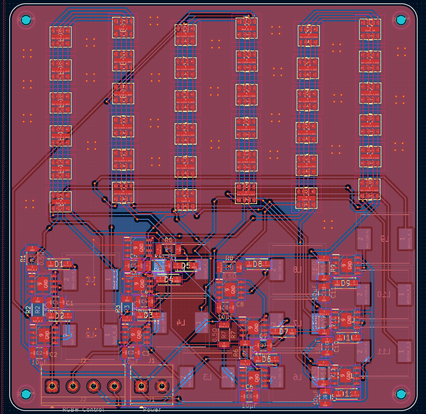
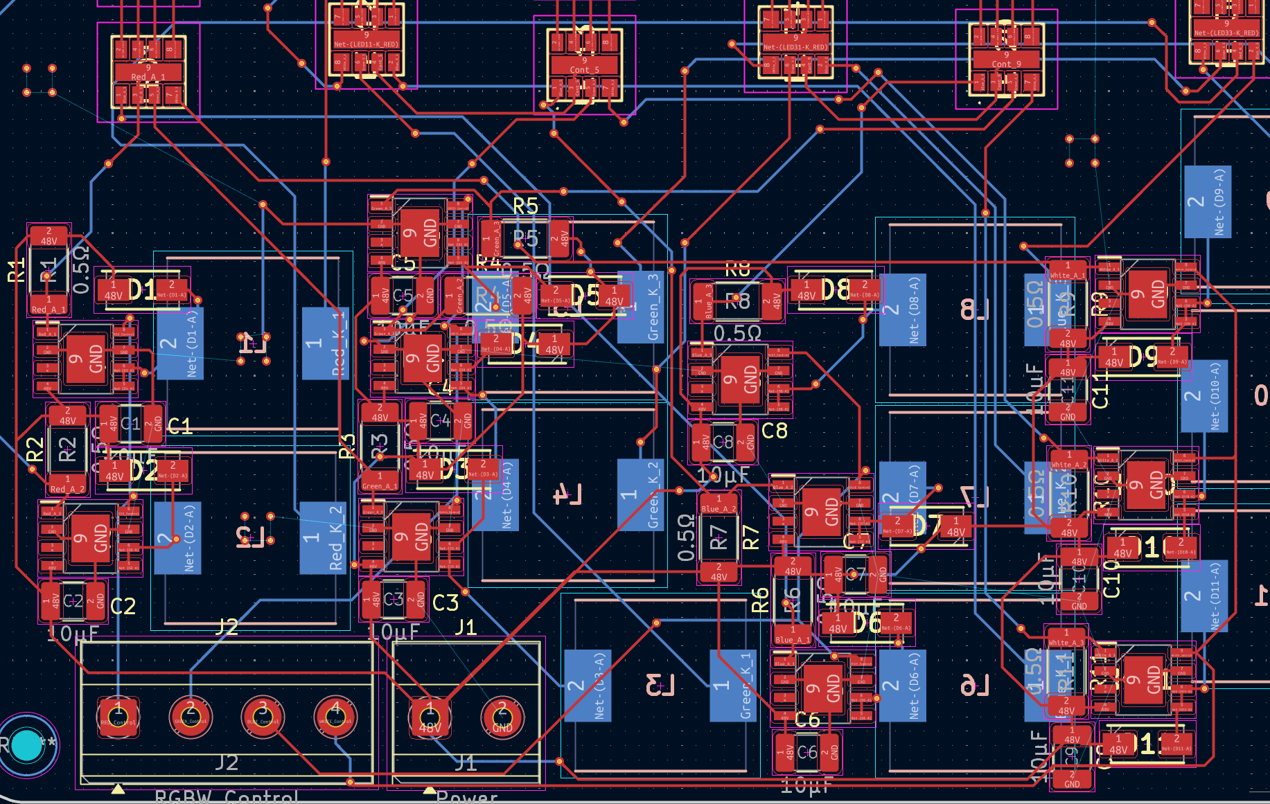
Finishing off the PCB was not particularly easy but it (hopefully) should be functional! Here's some crazy routing (with the GND plane removed)
Time spent: 22hrs
July 2nd - @ConfusedHello
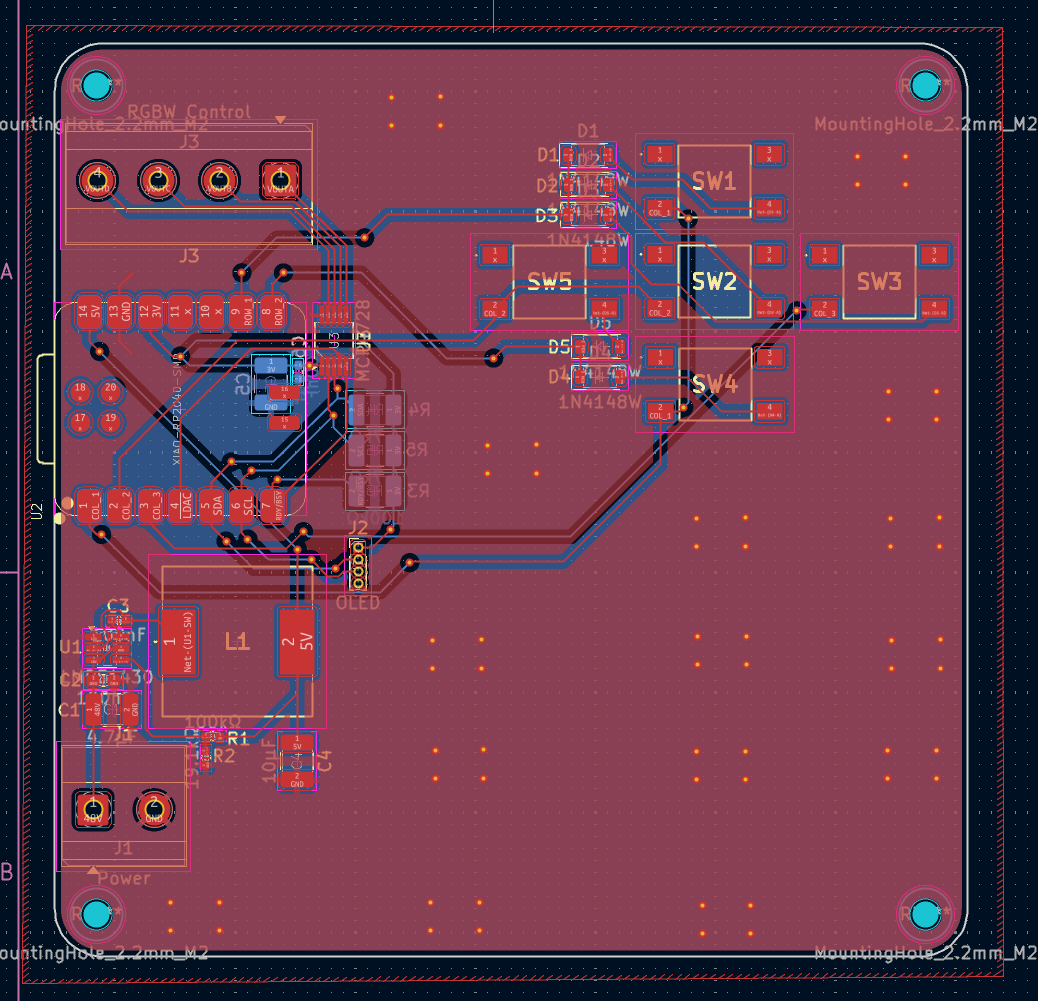
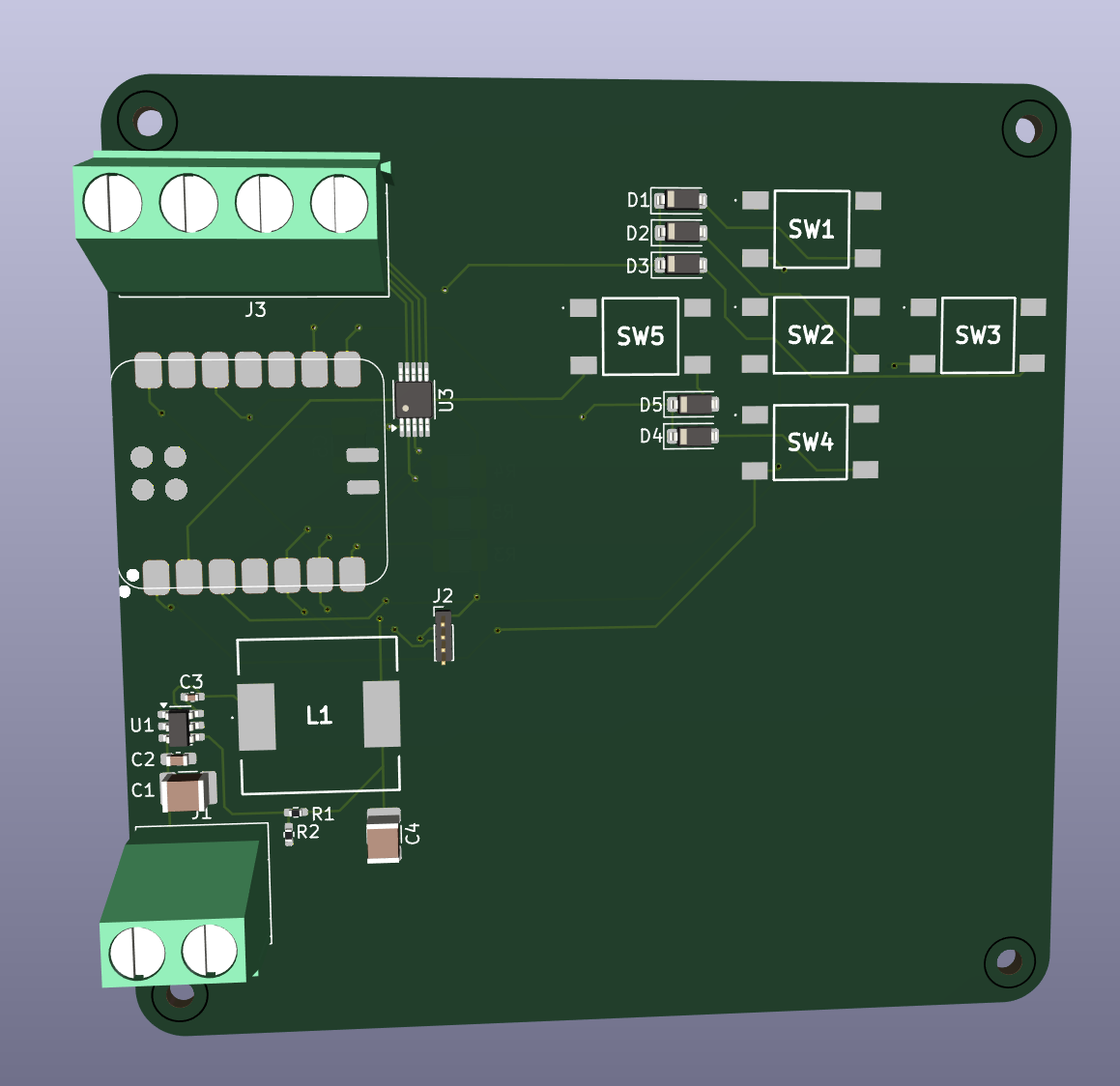
Another full day spent on the project - practically the entire day from waking up to going to sleep. Made the control board schematic and PCB today!
The control board will use a XIAO RP2040 MCU, along with a DAC for precise RGBW intensity control (voltage control). The PCB layout for this board was honestly not the worst I've done. There's also a 5V regulator circuit for the MCU and DAC.
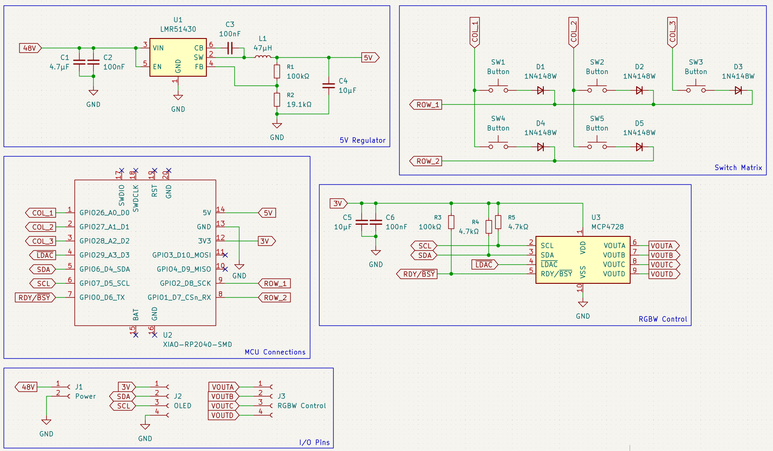
Also managed to write the software for the MCU today now available in \src\Software
Time spent: 14hrs
June 30th / July 1st - @ConfusedHello
Journaling two days at once here (mostly because I was up until 2am looking at plane tickets) but as a quick summary of what's happened the last two days (would prefer nice, longer journals but timeee), the initial research involved looking at current commercial products and planning a little into how we're going to do this. A few things we looked at include:
- Important information about film lights! This includes brightness, CRI, DMX. One important spec is the Color Rendering Index which determines the accuracy of skin tone under the light. Typical film lights are ~96CRI.
- RGBW LEDs! I think I've settled on the Lumileds L1MC-RGB2290500MP0 for their 90CRI (not particularly good for filming but still better than all the other 70-80CRI ones). The 2200K (warm white) temperature isn't the best but I imagine we can get around that by utilising the RGB colours more when going for a cool lighting and utilising the white more when shooting warm.
- LED drivers! From the looks of it there doesn't actually seem to be all that many for me to choose from that support the max ~200mA current but 120mA If should do okay (this is the max for the drivers I've found). The TLC59116 should be okay for this project.
- The case and stand I'm leaving the @Jayx2u - they'll be designing the case, as well as the mounting solution for the light and other misc. components (such as fins).
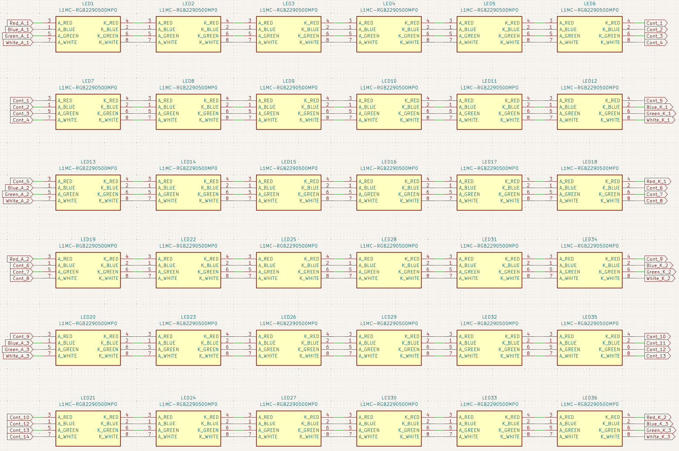
A lot more research later the setup will most likely be 36 LED packages per board (6x6 grid) and current controlled from 48V, continuing on with the research, A LOT of things were scrapped in the process such as suitable DC/DC buck converters (for 3.3V and 4.5V) when looking at parallel LED drivers before landing on the current (simplified), more efficient solution: driving the LEDs directly from a 48V supply with current control. This high-voltage approach minimizes current requirements, while also reducing trace widths on the PCB.
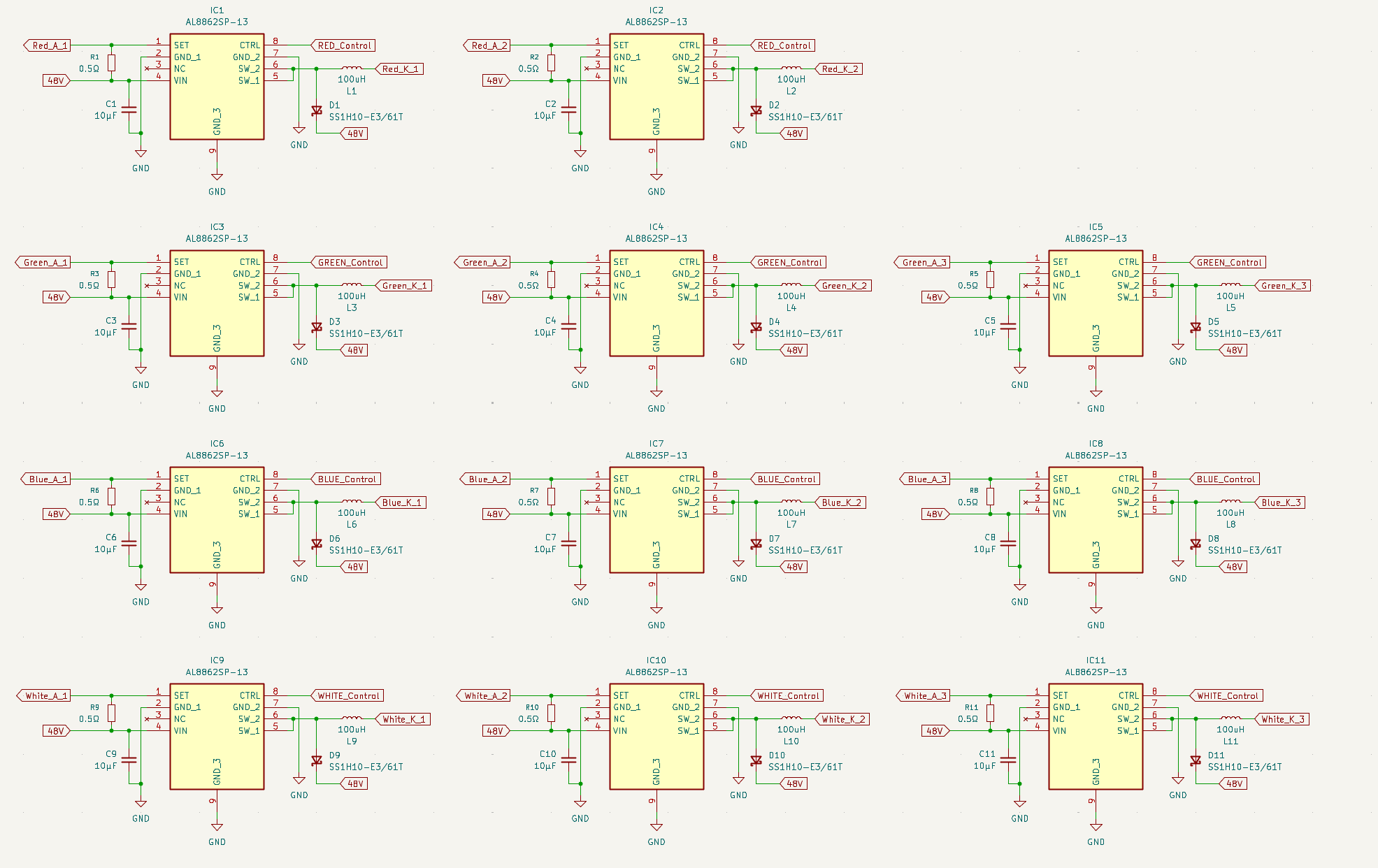
Considering that we have a 48V supply let's calculate the amount of chips we'll need to power this board.
48V supply for 36 LED packages (6x6 matrix)
LED specs:
Red - 200mA @ 2.25V drop
Green - 200mA @ 3.55V drop
Blue - 200mA @ 3.3V drop
White - 200mA @ 3.3V drop
2.25 x 36 = 81V drop ... 2 channels (40.5V drop each)
3.55 x 36 = 127.8V drop ... 3 channels (42.3V drop each)
3.3 x 36 = 118.8V drop ... 3 channels (39.6V drop each)
After wiring it up in KiCad:
And the controllers:
Will speedrun the rest of the schematic and PCB tomorrow maybe? Time to finish up for today though as it's almost 1AM.
Time spent: 18hrs
June 29th - @ConfusedHello
It's 2AM in the morning and I'm calling you now making a new Git repo! Today was some initial research to determine if the project was achievable and some other general information relating to the project. Also, happy to bring @Jayx2u onboard this time! We'll be working on this project realistically over the next two weeks to (hopefully) make a decent film light for our planned upcoming video!
Time spent: 3hrs