
Omninado
Omnidirectional and omni-purpose robot built on ROS 2
8th to 9th August 2025: Create Power Delivery PCB
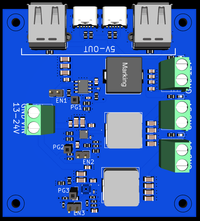
I spent these two days creating a power delviery PCB for the robot that can take an input of 14.8V from the battery pack and step it down to 12V, 6V, and 5V.
TI's Power Designer was extemely helpful while desgining this PCB, it helped me select the best ICs for the job, alongside giving great recommendations for the passive components.
I used the following ICs: LMR33640ADDAR (12V), TPS51396ARJER (5V), TPS51396ARJER (6V).
I learnt a lot about PCB heat-sinking during the process, alongside choosing the copper density and the width of the traces on the PCB.
The power delivery PCB will be placed directly on top of the motor driver for now.
 |
 |
|---|---|
| PCB 3D View | Schematic Diagram |
Total time spent: 10h
30th July to 1st August 2025: Complete 3D Model
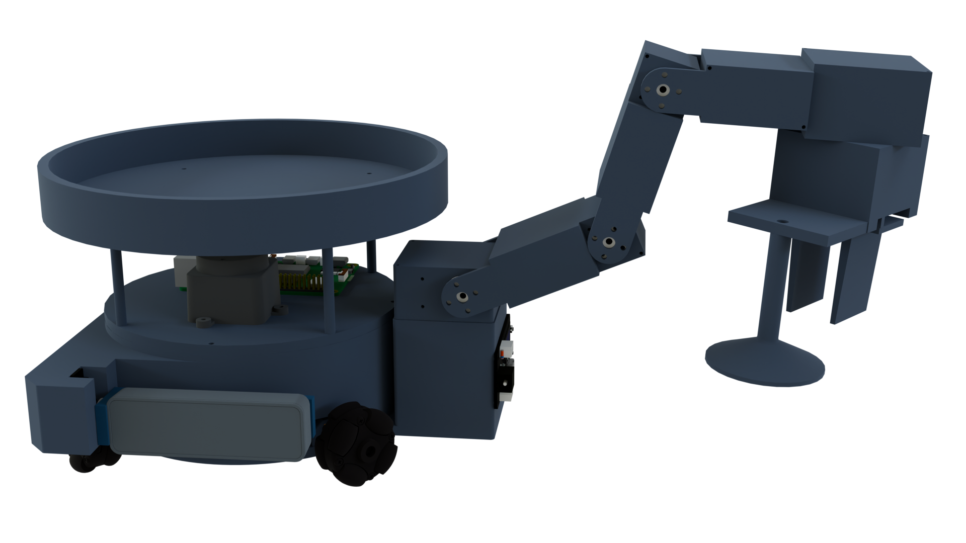
I spent these 3 days completing the 3D model of my robot, it is now ready for its first print.
I have added ways to mount everything needed (motors, omni wheels, motor driver, rotatable depth camera, lidar, raspberry pi 5).
Motors and Wheels: Luckily, I was able to find incredible models for the motor clamps, the N20 motors, and the exact omni wheels with their coupling that I was using online. I took various measurements of the clamp and accordingly created screw holes on the base of the robot. Then I went into the assembly workbench and got everything attached!
Motor Driver: This is a custom driver that I have created. I imported its STEP from KiCad, measured distance between the screw holes and accordingly added them to the base.
Depth Camera: This was by far the hardest part of the entire robot. I had to take a lot of measurements of the servo and depth camera to create the mounts as accurately as possible. I had to rework it about 2-3 times, as I was unhappy with the final result. The sketches were also pretty hard to make as I needed to create an extrusion on a circular base.
Lidar and Raspberry Pi 5: Got the lidar's model from waveshare and the pi's from thingiverse. The major difficulty was accommodating them in the small space at the top of the robot. But I eventually figured it out after a bunch of trial and error.
I also added a roof to the robot to make it easy to pick the robot up and for the roof to also act as a place for the robot to keep items it picks up.
Updates Regarding Related Projects
- I spent a lot of time on the robot arm to be used for this robot (Omni Arm) and it is also ready for its first print.
- The
omni_wheel_drive_controllerhas been merged intoros2_controllers.
Total time spent: 20h
5th July 2025: Added velocity limits - cmdvelcontroller
There were no updates for a while as I was working on various things that will be used in this project. Here is a list:
- ESP32-S3 6 Motor Driver with IMU: This is the microcontroller shown in the Movement Control Diagram.
- ESP32-S3 6 Motor Driver with IMU - Library
- multiomniwheeldrivecontroller
- cmdvelcontroller
I made an update today as I have added velocity limits to the robot. This is a part of the cmdvelcontroller as shown in the Movement Control Diagram.
Total time spent: 1h
18th June 2025: Created Movement Control Diagram
Today I created a diagram showing how the movement of the robot will be controlled.
 |
|---|
| Movement Control Diagram |
Total time spent: 1.5h
12th June 2025: Got Basic Simulation Working
Today I did the following things:
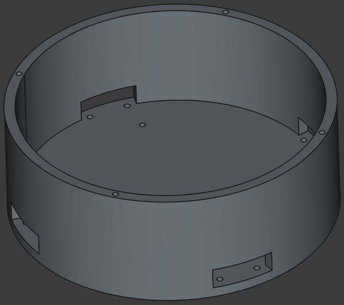
- Created the 3D model of the base of the robot.
- Wrote the ROS robot description.
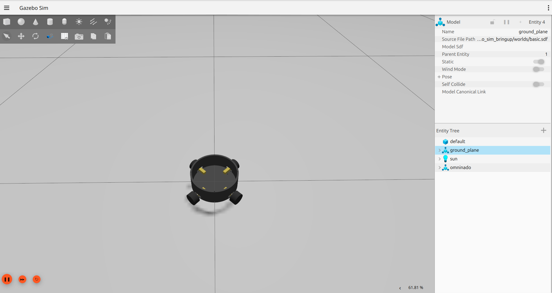
- Created the packages and launch scripts necessary to get the robot simulated in Gazebo.
- Configured ros2_control to get the robot moving in simulation, I used the multiomniwheeldrivecontroller that I made in the past.
- Wrote some documentation.
 |
 |
|---|---|
| 3D Model of Base | Robot in Gazebo Simulation |
Total time spent: 8.5h