
DLSR Gimbal
A DIY Gimbal for a Full Frame Camera!
Total time spent to date: 60hrs
June 18th - Final Design Update
Hello again - it's been a while. I've been focusing on my other project, USB-Mic recently - then I was sick for a week. Then there was the state-wide GAT (the memes are crazy).
Anyways, for the final journal entry for the design, I present: THE PANEL
 . I will be submitting this today!
It's been a crazy last few weeks working on this project - looking forward to (hopefully) building it soon!
Time spent: 8hrs
June 5th to June 9th - Final Prep
A few things these last few days! Did most of the final prep for submission last Friday and today. Had the zoom call as well a few days ago! Continued working on the BOM on LCSC for the PCBs. Also look there's a README now!
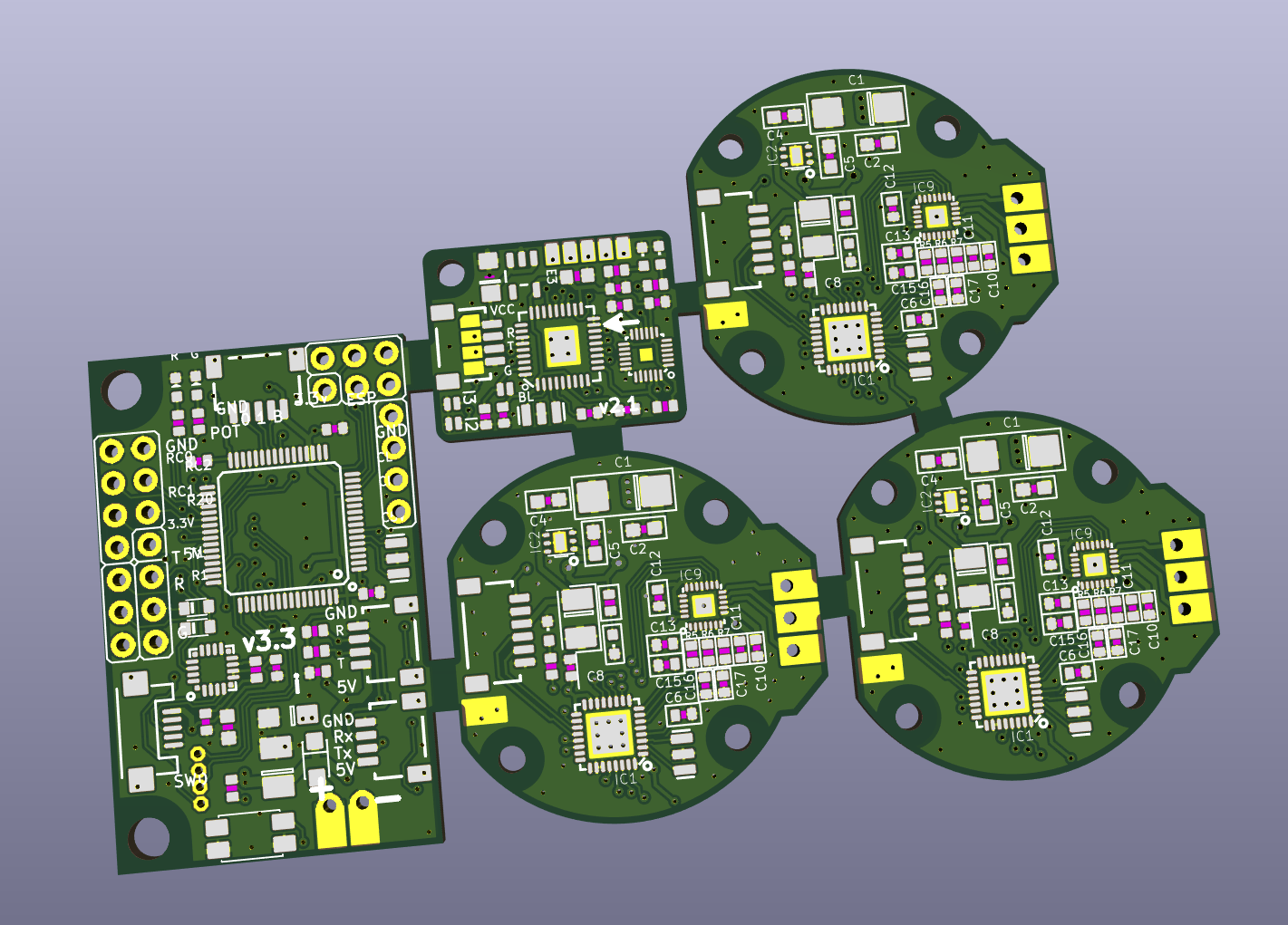
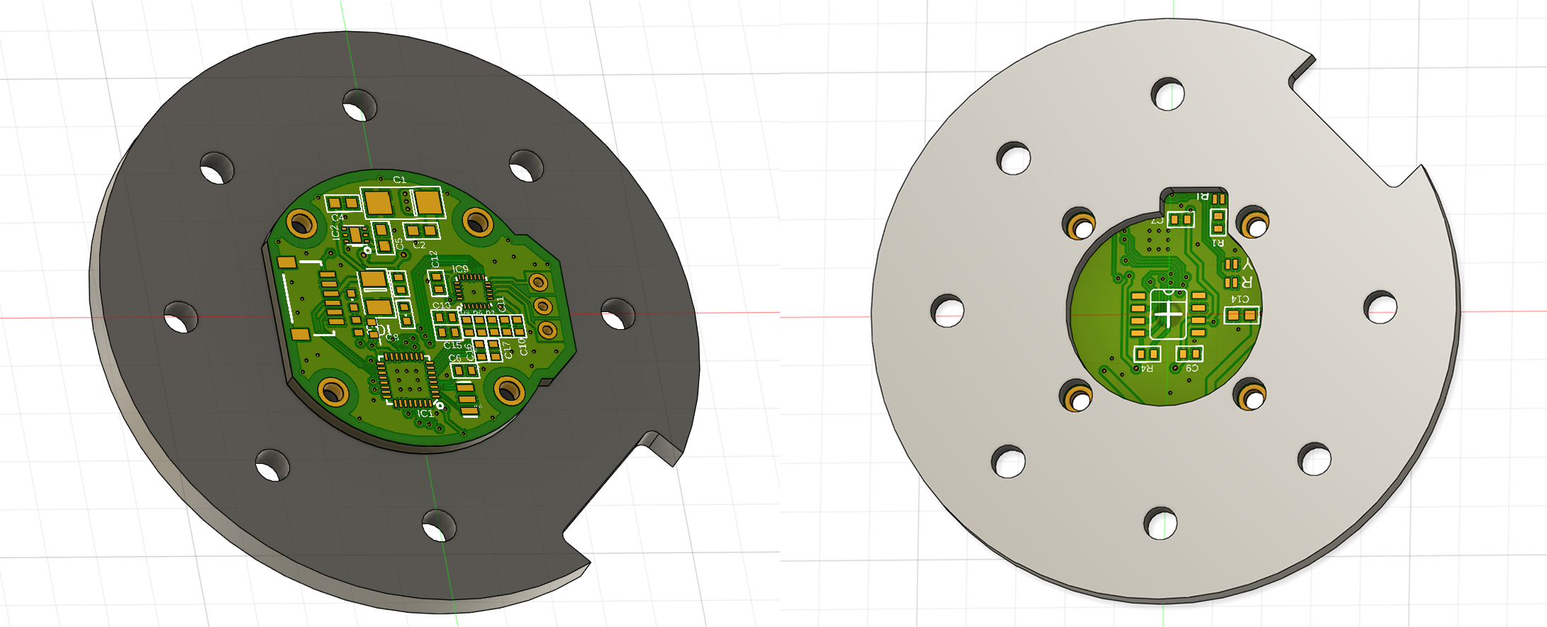
I've also been panelising all the PCBS (3x motor controllers, a BGC and a IMU module) into a 60mmx100mm panel (I swear this is taking ages) so I don't have to pay for 5 seperate JLC orders. PCBA is also out of the question as the amount of time it would take to properly set up all the footprints would be crazy, so I'm grabbing a stencil from JLC and will be attempting to soldier the board with a hot air rework station at school.
I feel like the finish line is close - just a few more days to finish off the panel!
Time spent: 10hrs
June 4th - Git merge
Spent some time searching for the components for the PCBs as well as a few other misc. components (phone mount for display, LiPo etc.) The completed BOM will be available in the README.
Time spent: 3hrs
June 3rd ...
Time spent: 2hrs
June 2nd - Git branch
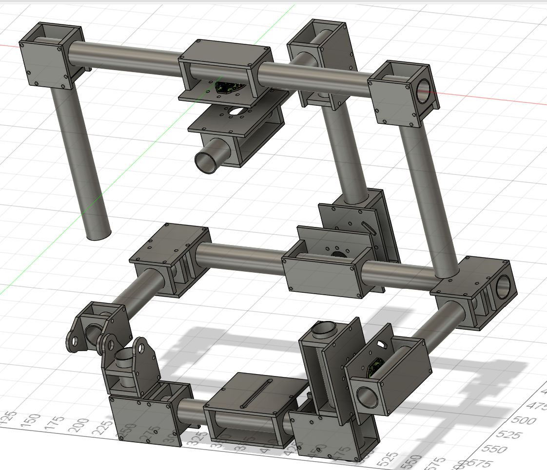
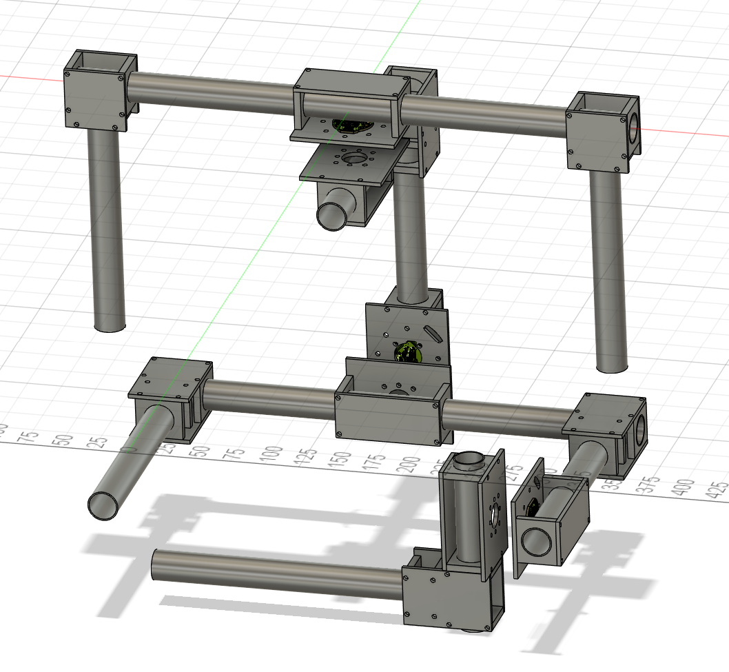
Well today was one heck of a day! Frame is done, and it's BOM has been roughed out! Tommorrow I'll most likely spend a little bit of time on the PCB BOMs but I don't expect too much time to go into it. Now behold, the completed frame in all it's non-rendered glory!
Just one issue however. When I started building the project, the clamps I found (literally only one listing on Aliexpress) were apparently $1.5 each (I even added them to cart and went to pay just to check). Unfortunatly they're now listed at $7.50 for 2??? Meaning I need about $160AUD of clamps?
Update from later: found 1 other listing for 1.7AUD for one? Totals to $74.8 - a lot more reasonable. PCB work continues tomorrow!
Time spent: 5hrs
June 1st - Git push
Happy April fools! Wait no it's June... Anyways, Started off today by redoing the base mounts for the motors, I decided the double-clamp was a bit excessive even if I erred on the side of caution. I also realised, the 90° could also be easily accomplished using the same method as the motor mounts! So, after a few hours of work - the gimbal modeling is yet another step closer to being done! Also spent some time sanity-checking some carbon fibre panel/tube prices while I was at it.
Tomorrow will focus on the camera mouting plate (should be pretty easy) and the joint for the other side (still don't know how that'll work to be honest). In the coming days I'm planning on finalising the PCBs as well as confirming a BOM + price. Project is over going pretty well and I'm feeling good!
Time spent: 5hrs
May 31st...
Worked on some modelling and re-thought the 90° joints. Will elaborate tomorrow.
Time spent: 2hrs
May 30th - Git commit
So much designing today! Started off by creating a quick reference model for the tube clamp I managed to find.
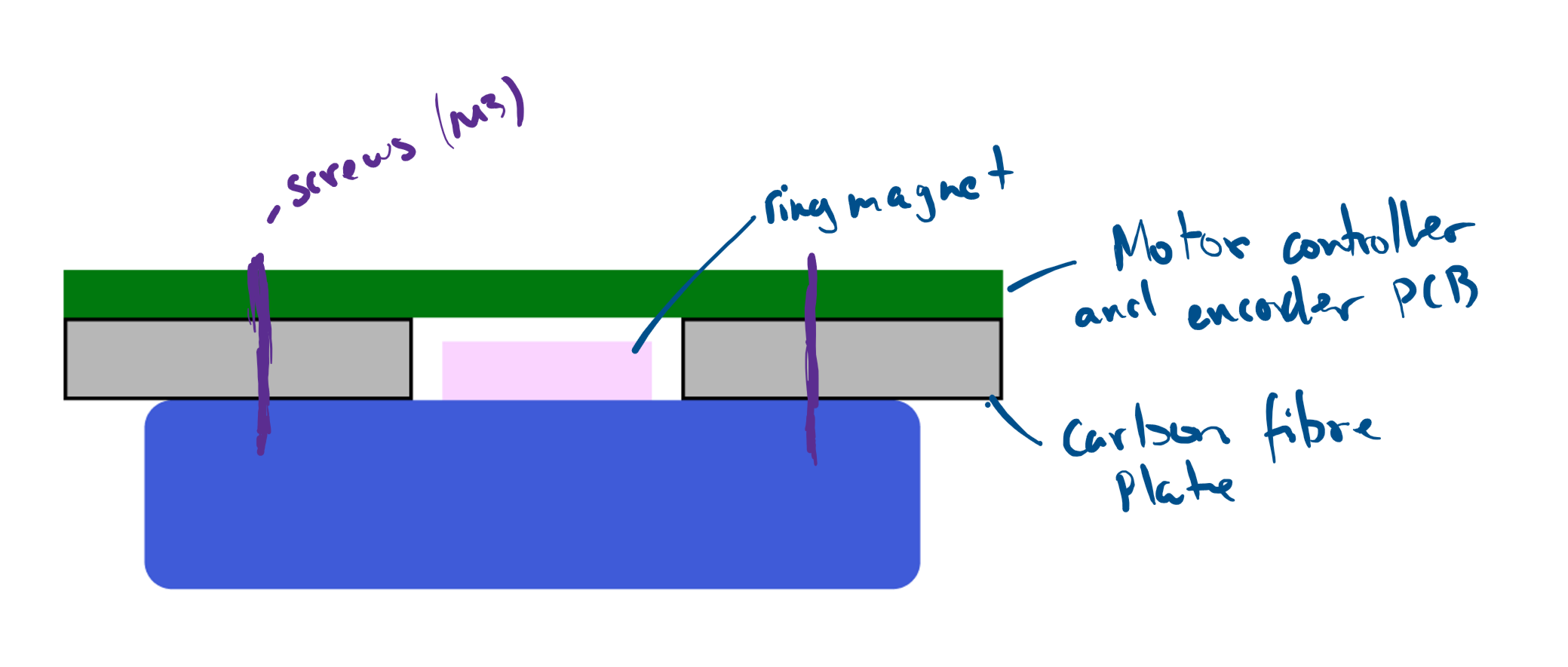
Next I moved onto a mount for the motors, here's where I realised that the motor controller modules that were designed with the in-built encoder in mind had non-optimal placement of the plug - it was on the side of the board with the encoder. So it's time for some KiCad-ing! Here's the end result of the motor controller / encoder PCB.
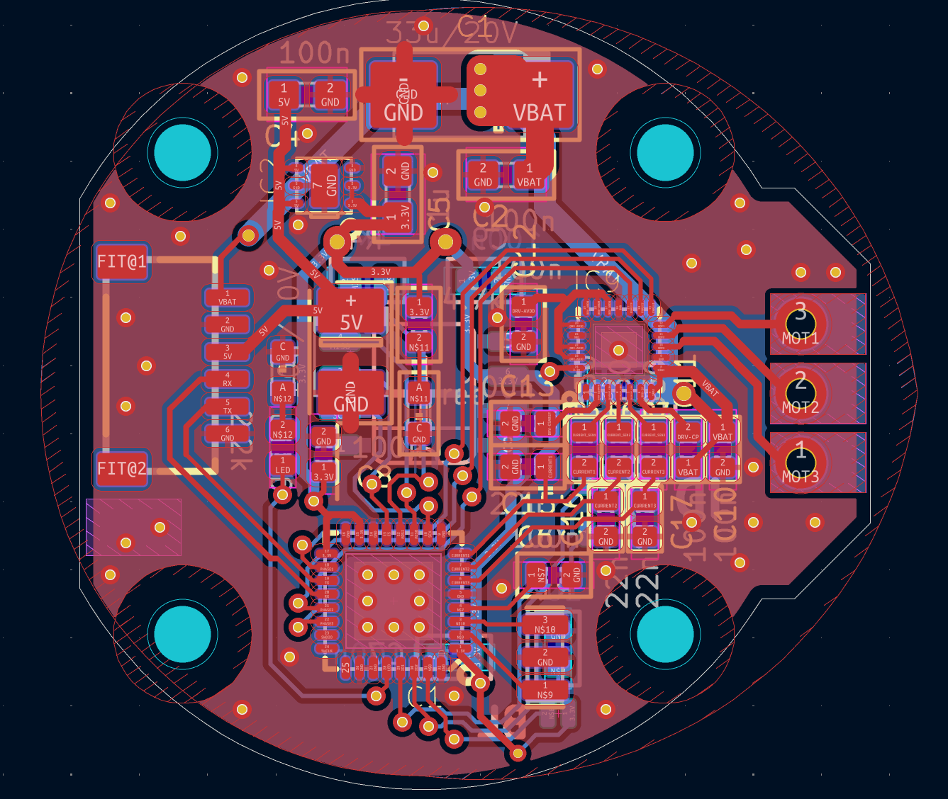 More details on these boards can be found in my repo here.
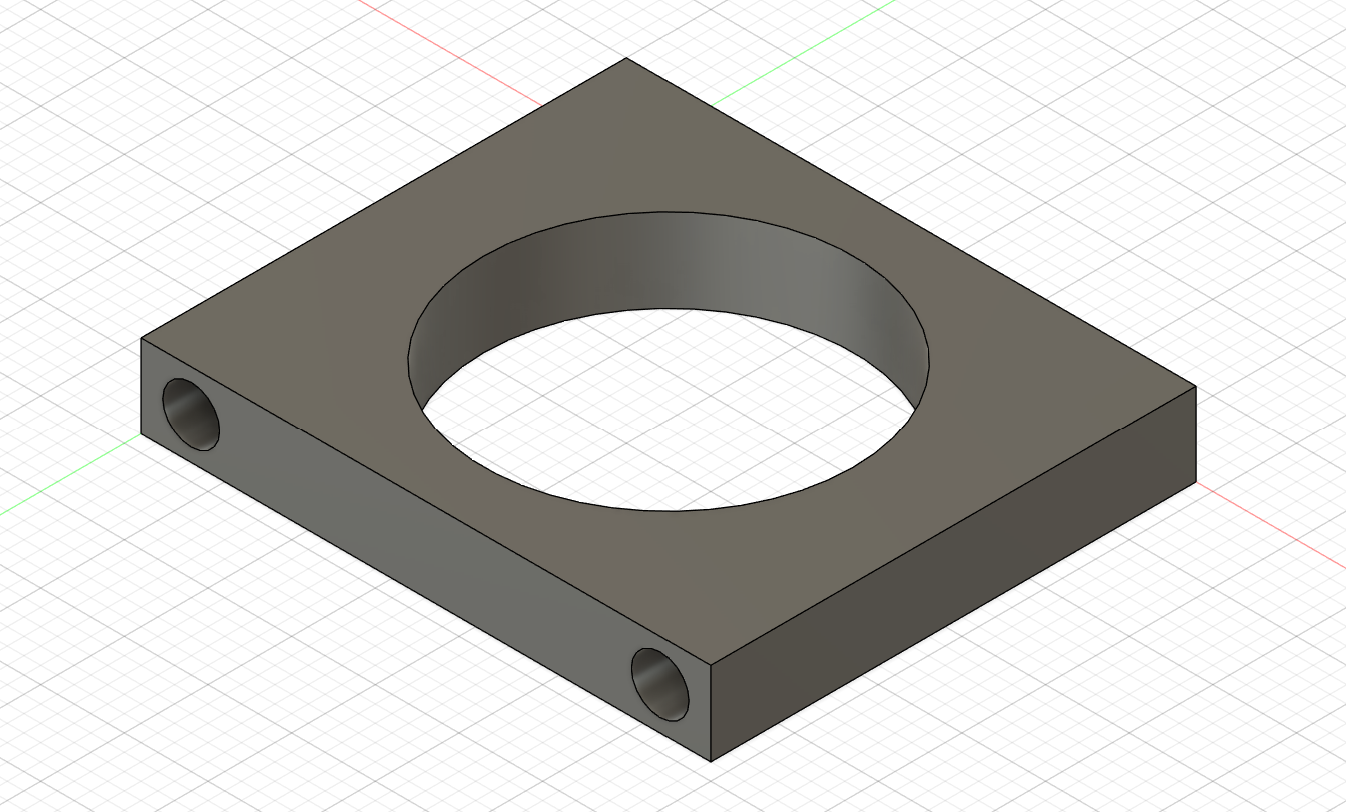
My next job was finishing up the design for the motor mount in Fusion360. The plates will be cut from a 3mm sheet of Carbon Fibre, allowing for a perfect distace between the magnet and the encoder (0.5-3mm).
Nice! Now we have the basic component for mounting our motors to! Next, let's work on the mounting plate for the other side of the motor (the side that spins) and start putting a few things together!
After designing a mount for both sides of the yaw motor, let's try having a quick look at what we're up to.
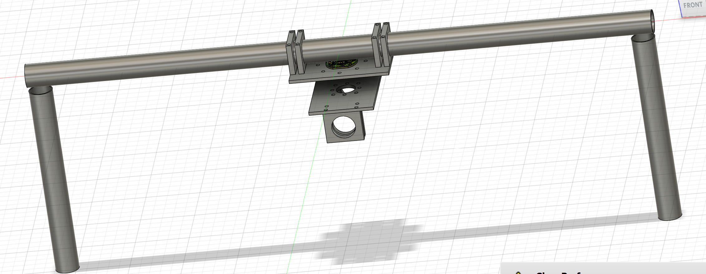
Not bad for the day! Tomorrow will focus on continuing to build on the gimbal design,as well as the camera mount + IMU.
Time spent: 10hrs
May 29th - Git add
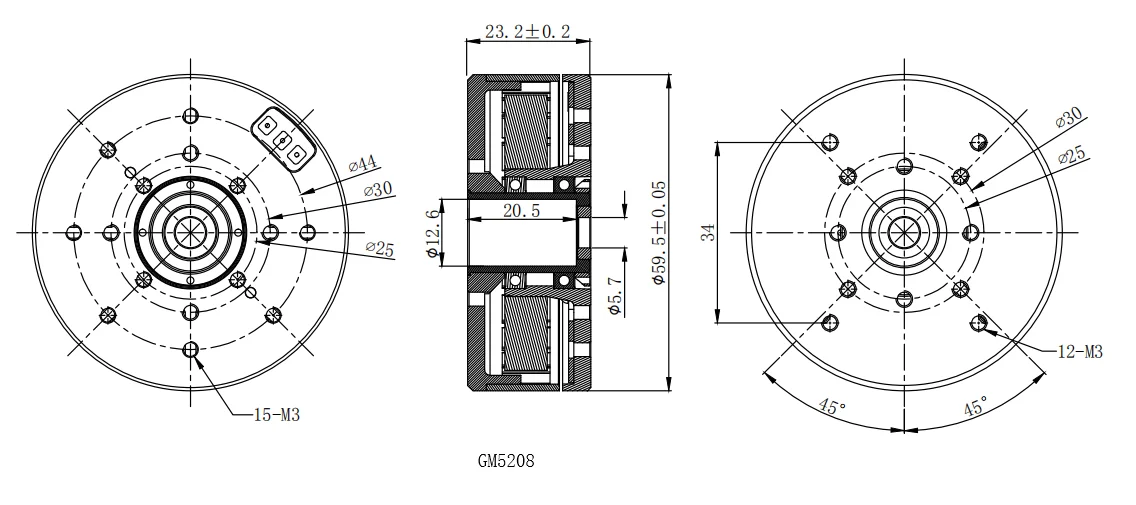
Finally ready to move onto some designing! After some more research I landed on the GM5208-12/24 motor. It's the standard motor from iPower's GM5 lineup, albiet not particularly cheap at approx $60AUD each ($38.66USD) it's the lineup made for gimbals and suits the job well. I'll add these to the newly-made BOM.
After a quick search online, I was able to find the dimensions for the motor online.
Next I deep-dived into the STorM32 BGC project, after looking through the documentation as well as the schematics of the components I settled on the T-STorM32 architecture and created the first draft of the gimbal layout and how it would be wired up.
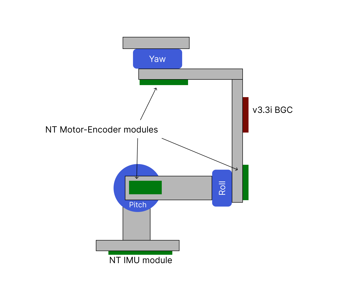
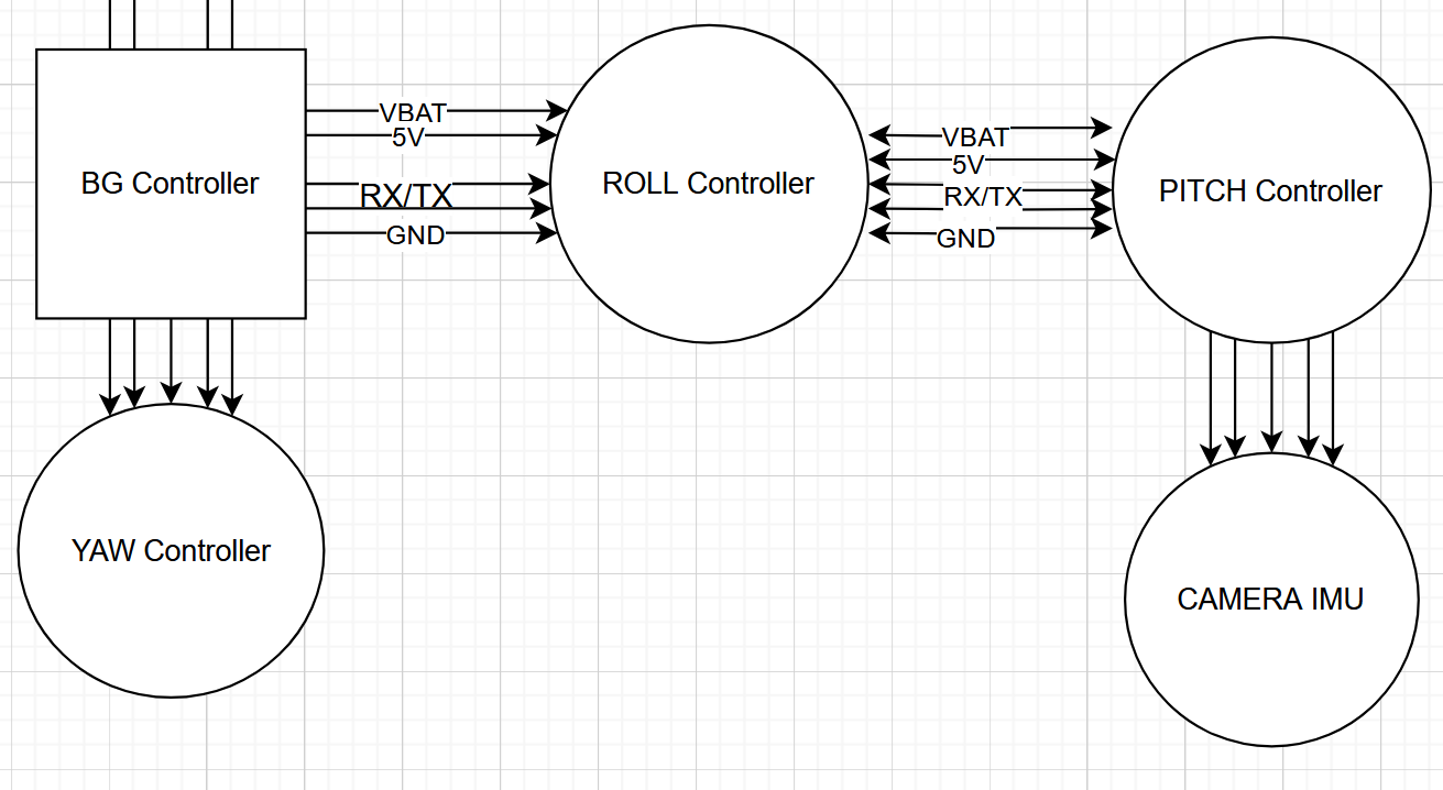
After some more planning for how the motor controllers would be mounted...
And for some quick ideas: - CF tubes instead of plates = cheaper - 90° joins using cut CF plates and screws - custom joystick + button pcb/mount
Time spent: 6hrs
May 28th - Git fetch
Spent most of today finishing off my hackpad. However, in the hour and a bit I spent today researching, there was a big discovery. The STorM32 project, a 2013 gimbal board designed... for drones. After some extensive research, I only found 2 examples of this board being used for a full-frame camera gimbal. The good news? It's open source, meaning I now have an excellent foundation to build upon for the controller side.
I now have the confidence to begin designing the frame, tommorrow I will begin by choosing a motor, then looking into designing an encoder PCB/frame for it.
Time spent: 2hrs
May 27th - Git clone
A lot more research research on existing DIY Camera Gimbals today! The main takeaway is that the manjority are actually two-handle gimbals. Why is that?
Once you've moved from light cameras such as a phone or action camera, they're a little difficult to hold in one hand, particularly if they're balanced above the level your hands are at (you can think of this like trying to hold a metal pole at a 45° angle in front of your body). Now when you switch to not only being able to hold it directly below your hand-level, as well as using two hands, it's a whole lot easier.
Spent today looking at basically all the existing DIY gimbals and their components, in summary: - For non-action camera gimbals, two-handle is the way to go - The MCU/ESC board that most projects use, the SBG32 (or an older version) are MUCH too expensive (approx. $300 AUD for one), so I'll have to design my own.
Will begin component selection (primarily the motors to use, as well as what the frame will be made of) tommorow to decide on the requirements for the MCU/ESC. This should be slightly easier than going at it with no experience due to some prior experience designing drones.
I'll also use this time to note, the name of the project isn't exactly accurate as I'm designing this for a mirrorless camera... Full Frame Camera Gimbal or something of the sort may have been a more accurate name. Looking forward to tomorrow!
Time spent: 3hrs
May 26th - Init
Today was primarily determining the viability and establishing the general idea for the project.
As I'm somewhat of a hobbyist photographer, I've considered the idea of building my own camera gimbal for videography as even second-hand on Facebook Marketplace they can be a few hundred AUD. However, I've never particularly had the opportunity (or funds) to attempt it spent all my money on cameras.
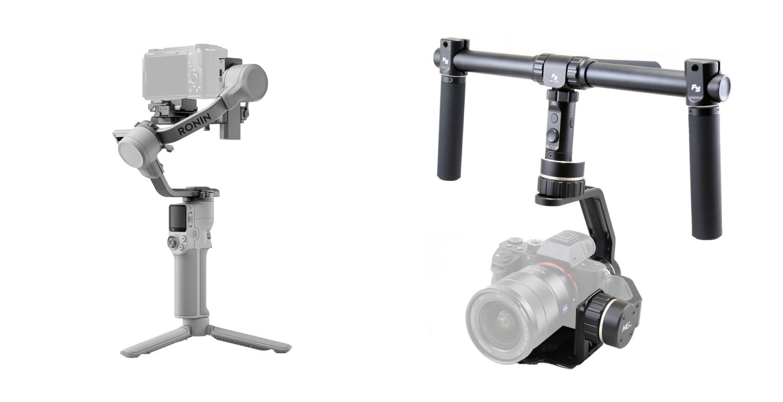
After some debate and sanity-checking my knowledge of a few DJI gimbals, we can now categorize the majority of consumer camera gimbals as either single-handle handheld gimbals or two-handle handheld gimbals. Images below, respectively.
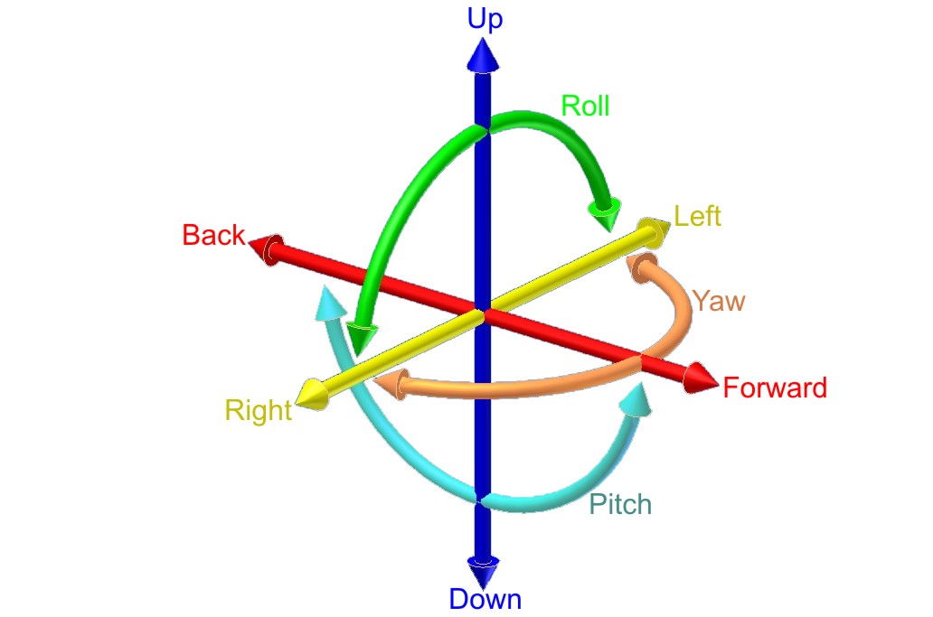
Now an observant individual may have realised both these form factors have one thing in common. They both stabilise the camera with 3 axis - pitch, roll, and yaw. Diagram by Horia Ionescu.
So while single-handle gimbals are easier to use for phones and your standard cameras (such as the Ronin S supporting up to 3.6kg), you'll never see one on a film set where wheeled steadi-cams, sholder rigs, and other massive gimbals are used.
So what do I actually need? (Hint: this is where we establish our scope) Personally, my camera setup without a cage weighs approximatly 1.2kg, well under the Ronin S' 3.6kg limit or the Ronin 4 Mini's 2kg limit - so a single-handle gimbal should do fine. We'll need it to handle somewhere around 2kg, so let's set that as our target.
To summarise: - I will be designing a 3-axis, single-handle handheld gimbal - The gimbal must support up to 2kg
Tomorrow's journal will probably not be as detailed as this one, definitely spent too long on it.
Time spent: 4hrs