
RoboHand
A robotic finger has 2–3 hinged segments moved by servos or tendons, controlled by a microcontroller and powered by a battery.
Total Time spent: 23h
June 26th:
I worked on my CAD. I had to really think about how to design the finger. I decided to start off with some cylidners and then processeded to hollow them out, cut them, connect them, then add the plates with holes for a string (kevlar line) to go through all the fingers, so it can pull and curl the fingers. I planned how I was going to design the whole finger and motion (sideways, and curling motion). I decided to use a string to curl the finger, by making a motor pull the string. For sideways movement, I will just use a servo motor probably.

Time spent: 1.5h
June 27th:
I completely changed my cad and tried to model an actual finger. I found a reference iamge so I worked off based off of that. This took a lot of tiem because I had to also develop parts for the bendable parts fo the finger. I had to use many different shapes and in the images atached, there should be one that shows how many different shapes I had to carefully plan out.


Time spent: 3.5h
June 28th:
I finished my CAD I think. I addee the hinges, I added the holes/guides for the kevlar string. I also added the holes for where I would connect the finger parts, and designed the tubes I need for that.


Time spent: 3.5h
June 29th:
I just added the servo motor holder (it took some time designing the holder for the servo motor accurately and also its axle's shape stuff) and the spool I will need to the CAD. For my final CAD file, I will take the stuff apart and put them separate so that the 3D printer can actually properly 3D print stuff.

Time spent: 1.5h
June 30th:
I designed the schematic for my robot finger/hand. I decided that all I will need is an ESP32-CAM module and a servo motor. So, I added those (it took some time to also add the symbol libraries and footprints too). I also realized I needed to add a capacitor as well. After runnign ERC, I received a few errors, so I fixed the unconnected pins with a No Connect end, and then also added the PWR_FLAGs. I was originally going to design a PCB too, but I realized that since it's just one finger, and also there may be some errors and refinning and testing and stuff, a PCB would take too long to make each time.

Time spent: 1.5h
July 1st:
I decided that although starting with one finger is probably good for testing and refining, I should still design the whole hand. So, for the CAD, I duplicated the figners and shrotened their lengths. Then I made the palm body and the base prism body to hold up the whole thing. Similarily, I changed the circuit schematic to incldue all 5 servo motors. I realized that I will also likely need to have a stronger 1000 µF capcitor probably. Next time, I will start working on the firmware coding, which will be complex since I need to code using the camera for hand + finger tracking.


Time spent: 2h
July 2nd:
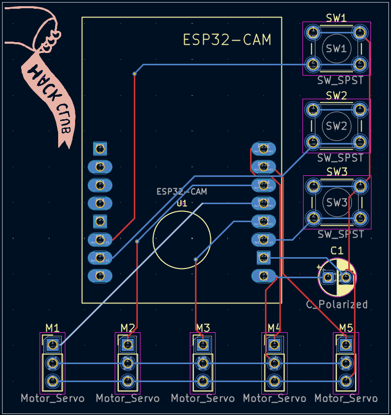
While I was coding, I realized I wanted 3 buttons to switch between different modes for the arm (hand tracking, computer command based, or preset gestures). So, I added the holes for the button in the CAD, then added the 3 buttons to my circuit schematic. After that, I designed my PCB. I'm likely not going to use a PCB when I build it just becauseits faster for testing if I don't, however, since the PCB looks nice and lcean, I just designed it too. I also worked on my BOM and README file. Finally, I worked on coding my software for this. I had to design the OpenCV code and make it compatible with teh ESP32-CAM. I had to also code the commands of the servo motor control which was much easier than I thought it would be since it is just setting angles, however, the calculations were very difficult to figure out and I had to use online sources. I had to also code internal pull-up resistors for the button because I was suggested by a friend to do that just to ensure stability. I learned quite a lot about the circuit schematics today as well, because I realized I hasd messed up my connections for everything, since I was just connecting based on the pin name, and not the GPIO number. I'm not done yet, but I am almost done.


Time spent: 3h
July 3rd:
While I was working on my BOM, I realzied that I will need a Female Power Adapter DC Barrel to Screw Plug Jack Connector, so I added that and also made a hole for it in my CAD. I also continued working on my coding. I actually used mediapipe such that the finger tracking would work this time compared to yesterday. I used a tutorial for this, since I am a beginner with mediapipe. I also had to follow a tutorial on how to use pyserial which took some time. The hardest part was converting the code to the esp32_version because I couldn't even test that python file. I also preprogrammed the different gestures which was actually pretty easy after I got the camera tracking thing working. I just copied the angles from there. I applied some error handling so that since I do not have the ESP32-CAM with me for testing right now, it would jsut print what signals or servo angles it would send.

![]()
![]()
Time spent: 2.5h
July 4th:
Before I submitted my project, I remembered that my original CAD file would get rejected because it was the fully built hand, however, in an actual 3D printer, everything would have to be separate and proper so there are no floating parts. So, it took me a long time making sure each part was separated into valid 3D printable parts. I had to take out all the hinges, the axles, the sides of the fingers, split part the body boxes, and more. I made sure that everything was not floating and would properly print. Also, note that for the body separated image, none of the parts are touching but they are very close to each other. That is just temporary. When I actually 3D print everything, I will separate those parts into different CAD files. This was a very time consuming and precise process.


Time spent: 3h
August 6th:
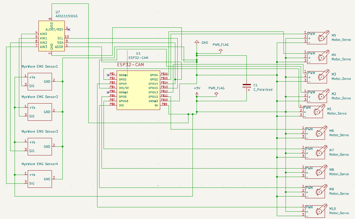
I changed the schematic because I realized I could fit in some EMG sensors, since I wanted to shift this project to a more mind-controlled robotic hand to make it more unique. So, I changed the circuit schematic and the BOM. It took some time figuring out how to fix the schematic though. I think the CAD is fine since I can put the motors within the hand and the arm. I also was able to find cheaper EMG sensors and so I updated the BOM. I did find a cheaper EMG sensor, but they only ship to India, so I emailed them and am waiting on a response.
Time spent: 1h